Lab 2: Phototransistors and Display

Objectives:
- Build a IR light emitting circuit.
- Build a IR light detecting circuit.
- Test the IR light detecting circuit with the oscilloscope.
- Test the IR light detecting circuit with the arduino.
- Build the other two IR light detecting circuits.
- Build and test the base station display.
Materials:
- 1 Robot from lab 1 including all the previous components
- 3 phototransistors
- 3 2k𝛺 resistors
- 1 60𝛺 resistor
- 4 4.6k𝛺 resistors
- 8 330𝛺 resistors
- 4 pnp 2N3906 transistors
- 1 IR led
- 1 SN74HC595N shift register
- 1 TDCG1050M 7 segment display
- 1 Arduino nano
- 1 Breadboard
- Wires
Phototransistor Circuit:
We are using phototransistors to detect and measure the frequency of an IR beacon. We installed three phototransistor circuits on the robot, facing forward, left, and right. Each of these circuits is a simple voltage divider, with the collector of the phototransistor connected to 5V, and the emitter connected to a analog pin as well as to ground through a 2k𝛺 resistor. All of the outputs of the phototransistors are connected together to a single analog pin, as the direction of the signal will not be important, and this allows us to use less pins. These circuits can be seen in the image below.

IR LED Circuit:
The IR LED circuit is very simple. We connect the signal generator positive to the Anode of the LED. We connect the LED Cathode to a 60𝛺 resistor to the ground of the signal generator. We then supply a 0V to 1.2V sinusoid from the signal generator at a frequency of 1khz. This circuit can be seen in the image below.

Testing the Phototransistor Circuits:
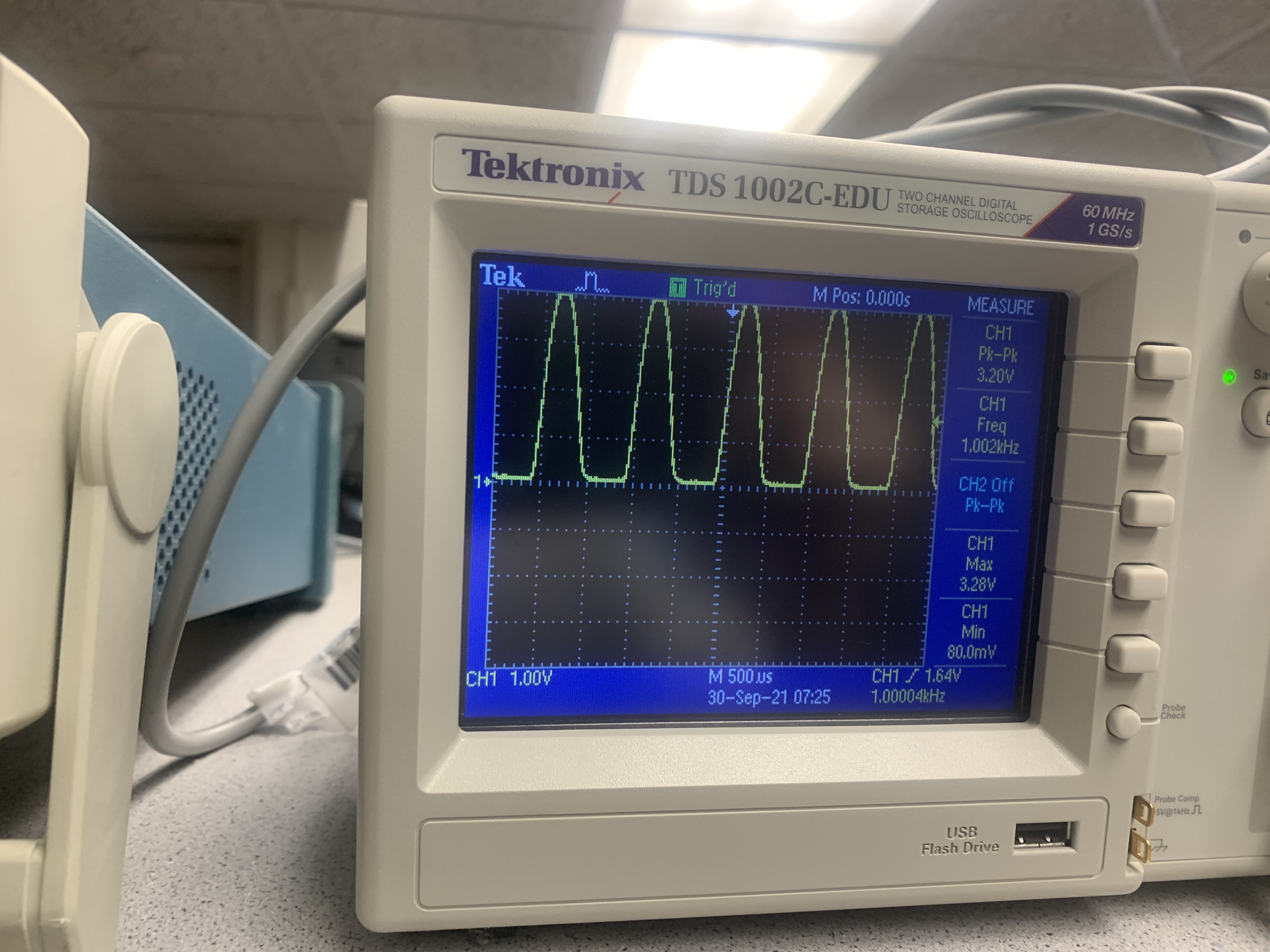
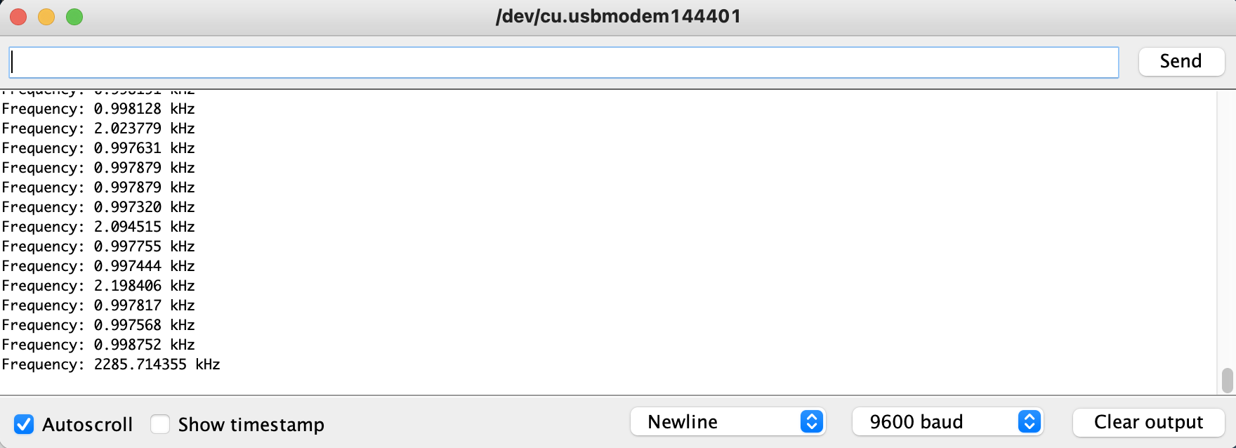
We next tested our phototransistor circuits. We turned on the signal generator (first image below) and checked the signal going into the IR LED circuit (second image below). Next, before connecting the phototransistor circuit to the Arduino, we connected it to the oscilloscope, held the IR LED near the phototransistor, and observed the voltage output of the phototransistor circuit (third image below). Finally, we connected the phototransistor circuit to the Arduino and used the ADC and TCB functionality to measure the frequency, before printing it to the serial monitor (fourth image below).


7 Segment Display:
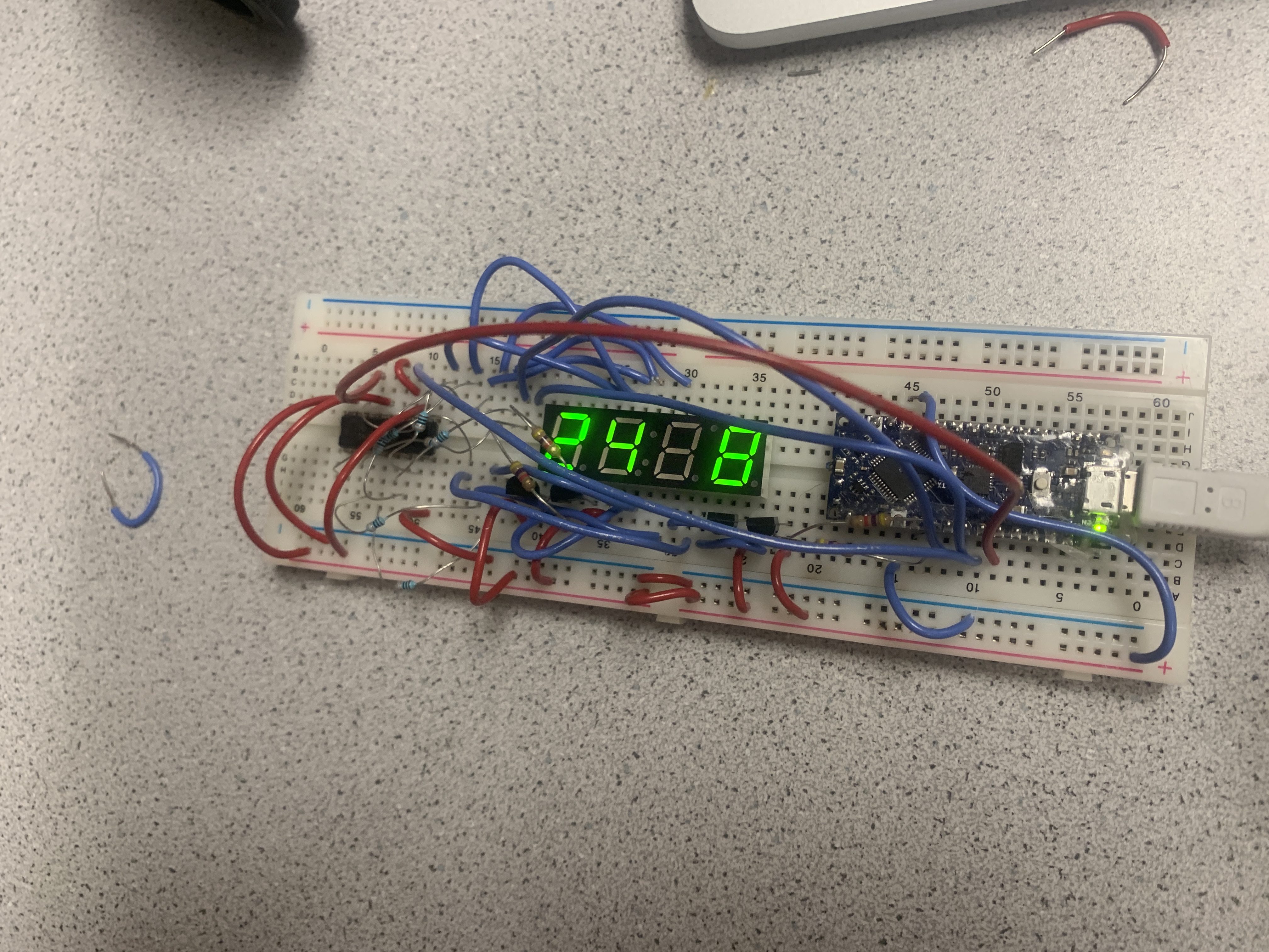
Next we started the base station circuit. We used a shift register to hold values to be sent to the 7 segment display. We used a series of transistors to control which digit was active, so we would not draw too much current from the Arduino. This shift register meant that only one digit would actually be powered at any given time. This can be seen in the image below, as one of the digits appears off, as my camera’s exposure time was not set long enough to capture every digit, although in person they all looked on. We also programmed the arduino to take into account any necessary decimal points if the number is in the tens of khz.
