Objectives
- Start to program basic then more complex things on the Arduino Nano Every using the Arduino IDE
- Setup robot frame with servos and test them
- Install three ultrasonic sensors and optimally manipulate them to obtain distances in multiple directions
Materials
- Robot frame (mounted with DC motors to remove)
- Screwdriver
- Pieces of Velcro
- Two servo motors
- Arduino Nano Every & micro USB white cable
- Wood or other objects for walls
- Caster wheel
- 3 Ultrasonic sensors
- Screws, nuts, and washers
- Breadboard
- 3 AA batteries
- 9V Battery
Robot Frame Setup
To start the lab, the given robot frame needed to be setup with a couple basic components, including two servo motors with mounted wheels, a front caster wheel, and the AA battery holder and 9V battery fastened with Velcro. The frame came with DC motors and an old caster wheel already installed, so we removed those first before installing the new items.
After installing the servos, the robot had a nose-down profile, which was expected. It was also important that both battery components were installed with the correct orientation. The 9V battery was positioned at the front of the frame, and the AA battery holder was towards the back of the frame with wires pointing towards the back.
Breadboard & Arduino Setup
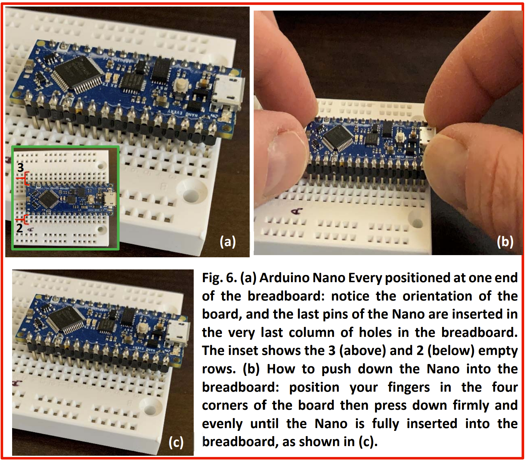
The breadboard was installed on top of the two battery components. We added wires between the vertically aligned power rails to have one source power the entire rail. Next, we positioned the Arduino Nano Every at the front of the frame as pictured below. We evenly pressed the Arduino into the holes of the breadboard, leaving holes on both sides to make connections in the future. To protect the exposed pins of the Arduino, we placed clear tape along the sides. Finally, to get our first look at the Arduino IDE and make sure the uploading process was working correctly, we programmed the Arduino with simple code that makes the onboard LED blink repeatedly. We were now ready to work with the servos.
Servos
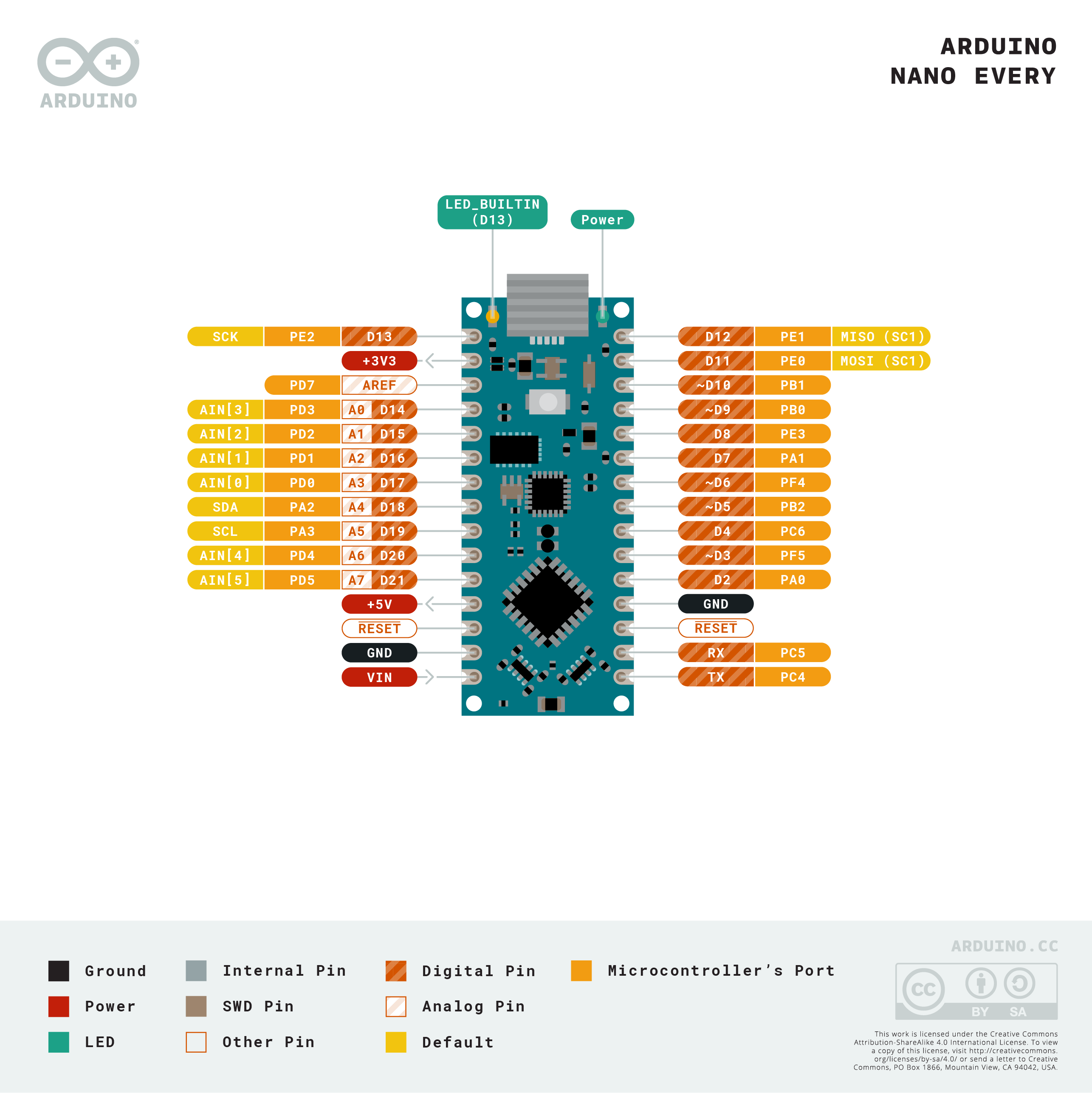
In order to manipulate the servos with the Arduino, we needed to use the Servo.h library provided in the Arduino IDE. It was also important to understand the pinout of the Arduino Nano Every so we could correctly send output signals to the servos. Pictured below is the pinout. For our servos, we used the D5 pin for the left servo, and the D6 pin for the right servo.
After becoming familiar with the Servo.h library, we wrote a simple program to complete the following task:
- Start in place facing North, motionless
- After 5 seconds, it goes North over approximately 20 cm, then stops, still facing North.
- After 1 second, it turns to its right towards the East in place by approximately 90 degrees, then stops, facing East.
- After 1 second, it turns to its left in place by 270 degrees, then stops, facing South.
- After 1 second, it goes South over approximately 20 cm, then stops, facing South.
- After 1 second, it turns to its right by 180 degrees, then stops, facing North.
Below is a video of our robot completing this task:
We had some problems with this part of the lab. The servos were not consistent with each other, so we had to drive one motor with a bit more than the other to achieve forward movement. Also, this lab relies heavily on Arduino’s delay function, which allows us to drive the motors with a particular setting for a set amount of time. The problem with this is that 90, 180, and 270 degrees were not linearly related with respect to the time needed to turn, so we had some trouble getting the robot to perform these turns and face in the correct direction. As seen in the video, some turns were slightly off, which we needed to address for the next parts of the lab.
Ultrasonic Sensors - Measure Distances
Each ultrasonic sensor requires a trigger input and an echo output, totalling to six pins coming from the Arduino. We will not have any pins left if we have an individual connection to each trigger and echo, thus we used a joined trigger where each US is triggered by the same Arduino output pin. We used the D3 pin for the triggers, and the D4, D7, and D8 pins for the left, forward, and right echo pins respectively. We used the 5V out pin from the Arduino to power each US.
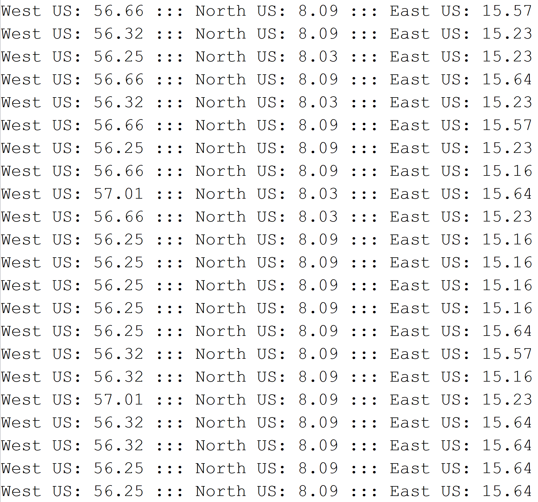
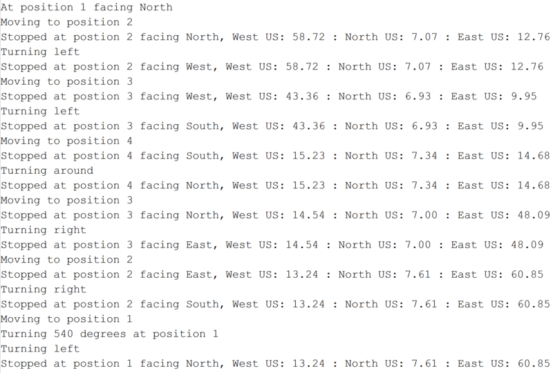
To test our ultrasonic sensors, we used a provided program with slight modifications to display the distances measured from each US to the Arduino’s serial monitor. We were tasked with measuring objects at different distances from each US and making sure each one simultaneously displayed the correct information. Below is a snippet from our serial monitor with the robot sitting at position 2 of the maze for the final part of the lab. These measurements proved to be quite helpful for finding the distances at which the robot was required to handle some task.
Ultrasonic Sensors - Navigation
With each US returning accurate distances, we now had to use these values to navigate a simple maze. The maze layout with position numbers is pictured below:
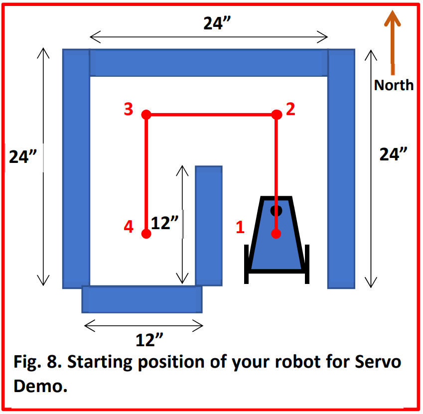
Our task was to navigate this maze, performing the following steps:
- Start in position 1, immobile
- Once the RESET button is pressed on the Arduino, it will remain motionless for 1 second, then head North towards position 2.
- Once at position 2, it will turn smoothly in place to its left to face West, then navigate towards position 3.
- Once at position 3, it will turn smoothly in place to its left to face South, then navigate towards position 4.
- Once at position 4, it will turn smoothly in place to its right to face North, then navigate towards position 3.
- Once at position 3, it will turn smoothly in place to its right to face East, then navigate towards position 2.
- Once at position 2, it will turn smoothly in place to its rught to face South, then navigate towards position 1.
- Once at position 1, it will turn smoothly in place to its left 540 degrees ending facing North where it will remain in place stationary.
During this navigation, the robot had to remain centered between the walls with no wobbling. The turns must be smooth. Also, the serial monitor must corroborate the movement of the robot, displaying the direction it is facing, position information, and the distances from each US. Below is a video of our robot’s navigation, with an accompanying serial monitor snippet:
We had a lot of trouble completing this part of the lab. We still had problems with the consistency of our servos, and our front US would receive small distances unexpectedly, which would cause our robot to handle a position prematurely. To fix the servos, we decided to change the power source from the AA batteries (which we suspected were low on power) to the 5V out pin on the Arduino. We noticed a significant improvement in both the power supplied to each servo and the consistency of each motor relative to the other. As far as the front US, we decided to reduce the frequency of trigger inputs. We suspected that we were sending too many trigger pulses at a time, causing inaccurate data from the echos. With the lowered frequency, the outliers were significantly reduced, but we then had a problem with too high distances coming from the echos. It turned out that the front US had become defected, and we replaced it with a new one, which worked well.
Another thing to note is changing the environments in which we performed the maze navigation. With limited time in the lab, we decided to build the maze at a dorm room and continue troubleshooting. Since the dorm room had a rug flooring instead of the solid surface from the lab, we had to adjust the speeds we were driving the servos with in order to achieve full turns and even movement.