Lab 1: Intro to Artemis
Objectives:
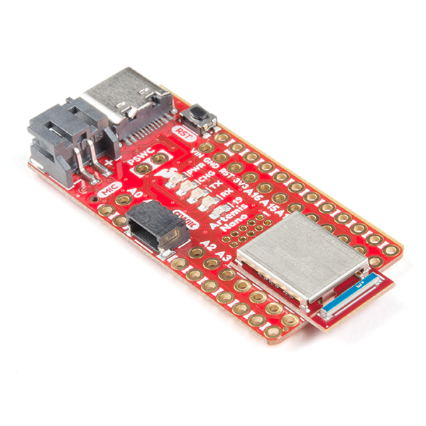
- Get familiar with the SparkFun RedBoard Artemis Nano
- Program the Nano to:
- Blink the LED
- Read/write serial messages over USB
- Display the output from the onboard temperature sensor
- Measure the loudest frequency recorded by the Pulse Density Microphone.
Materials
- SparkFun RedBoard Artemis Nano
- 1 x USB C-to-C or A-to-C cable
Artemis Board Specs
The SparkFun RedBoard Artemis Nano leverages the Apollo3 Microcontroller for its compute power and with the Sparkfun Apollo3 Arduino Core already built, it's compatible with the Arduino IDE making development lightweight and easy. Below are some of the features it boasts.
Examples
To get acquainted with the board, I ran a few examples on the Arduino IDE to make sure that my board was working correctly and to get an initial sense of the Nano's capabilities
Blink
As indicated by the title, this program blinks an on-board LED every second by setting the LED associated pin on the Nano HIGH or LOW with a full second delay in between each logical change. See the short video below for the output of this example
Serial
In this segment serial communication is established between the Artemis board and the computer using the two UART peripherals of the Apollo3 MCU. These peripherals can be used with Arduino Serial api to communicate. When performing serial communication it is important to set the Baud rate on the serial monitor to the same Baud rate defined in the code otherwise, you can't communicate properly with desired peripheral. View this short clip below for a demo of this example
Analog Read
The Apollo3 microcontroller includes an onboard ADC (analog to digital converter). The Apollo3 also has some internal ADC channels that allow you to measure:
- differential pairs
- the internal die temperature
- the internal VCC voltage
- the internal VSS voltage
In this clip, I used the delay() to slow down the printing rate to the serial monitor down to a period of two seconds so that the change in die temperature can be better seen. For Your Reference:
Microphone Output
This example demonstrates how to use the pulse density microphone (PDM) on Artemis boards. It leverages a math library for FFT computation and also the PDM.h library which takes care of converting an analog signal to a binary signal. Featured below is a display of varying frequencies as I whistle