Summary: This part concerns the construction of the robot, and a demonstration of the servos and ultrasonic sensors.
Construction of the Robot
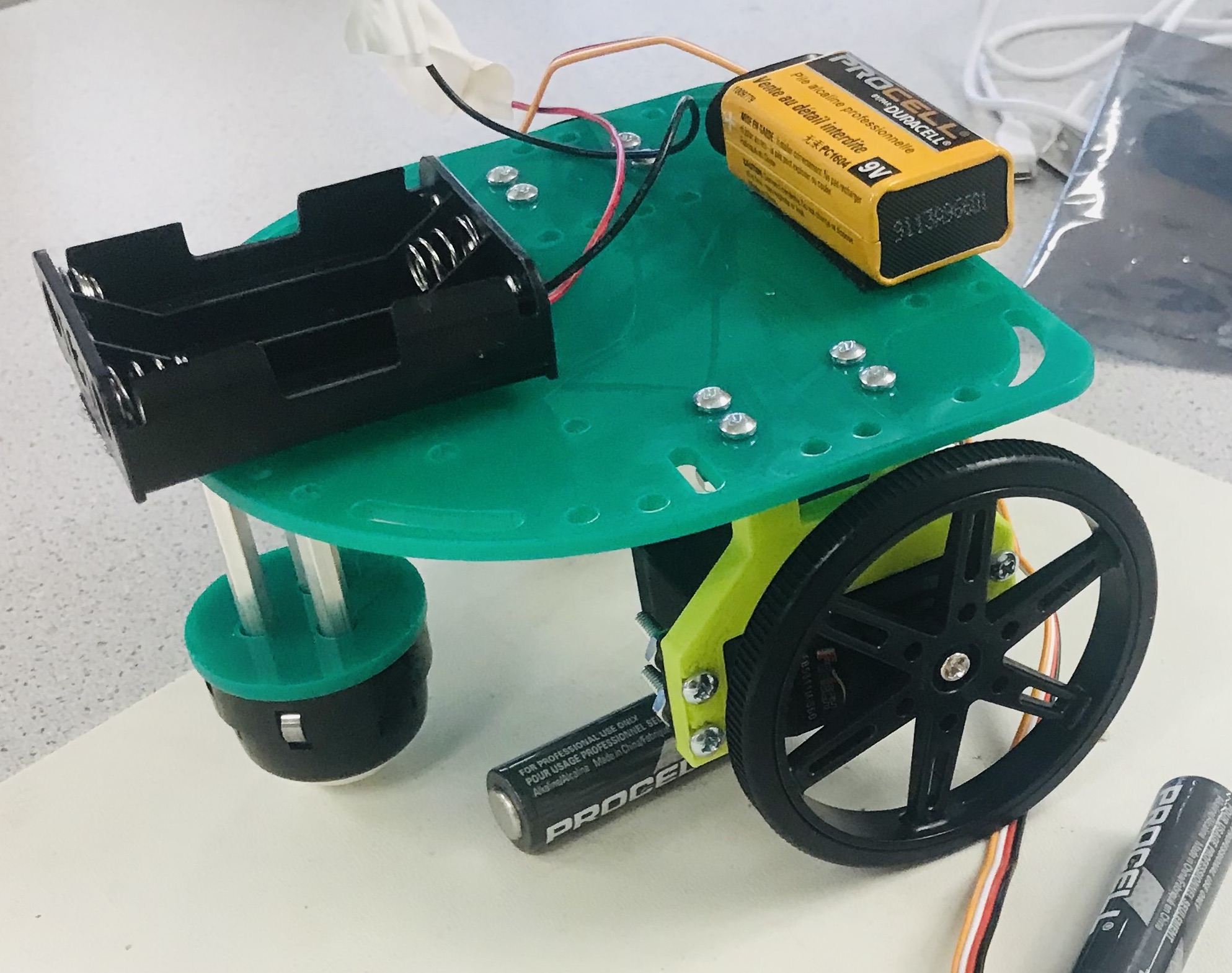
Using a supplied kit of parts, we constructed the cart, connecting the servo motor and caster wheels to the frame.
A protective layer of tape was put on the circuit board. The caster wheel was placed on the front of the frame, which was the curved side. The 3-D printed servo mounts were bolted in the back symmetrically. The servos were bolted on to the mounts, such that the axles were placed in the same position. Such an arrangement made the left servo operate backwards: writing 0 to it would make it spin back. This was kept in mind for future parts of the lab. The 9V battery and AA battery holder were stuck to the frame using Velcro, the 9V in the back and the holder in the front.
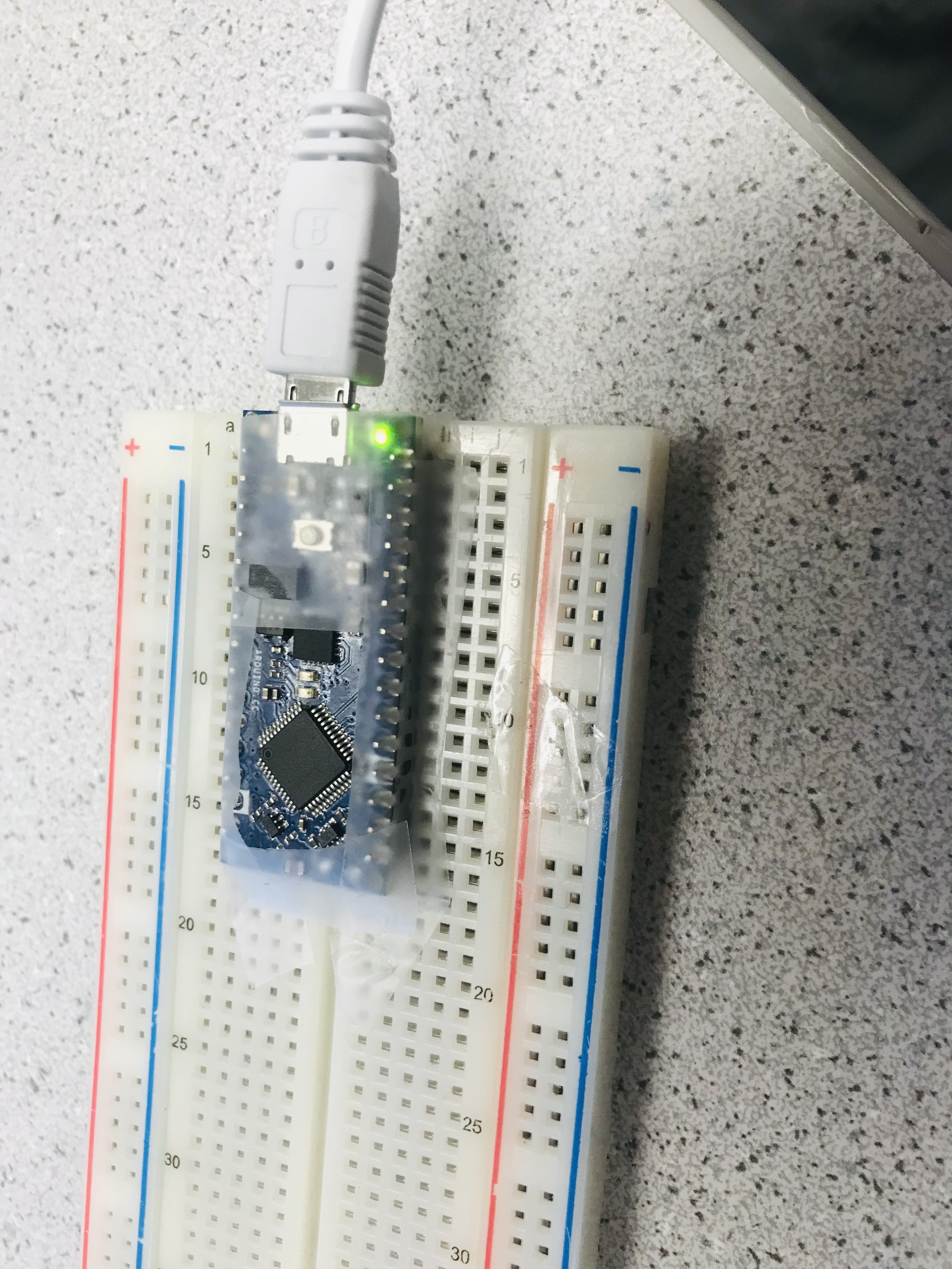
The Arduino Nano was placed across the center of the breadboard, such that each pin had it's own line of access points, and none were shorted. The edges of the Arduino were taped down to protect the connections from stray static electricity, keeping the top open to allow for heat dissapation.
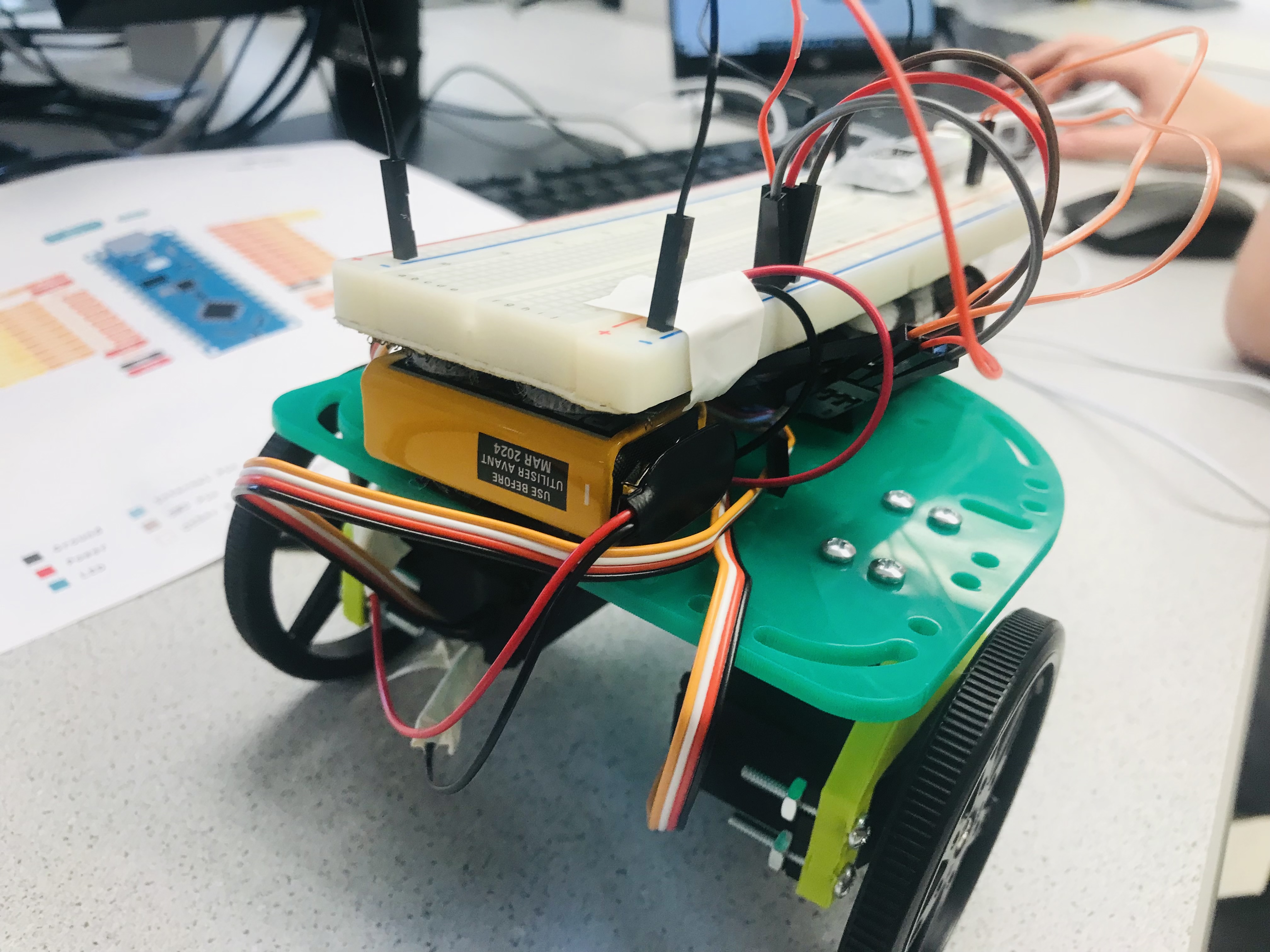
The breadboard was stuck on top using velcro placed on top of the 9V battery and the AA batteries placed in their holder.
-
Programming the Servos
Connecting the Servos to control them with the Arduino board, writing code using the Servo libraries to execute a given instruction set.
First, we replaced the 4.5V AA battery supply with a 6V one that fits 4 batteries. We then connected the servo motors to the Arduino board and power. VCC and GND on both were connected to the 6V battery supply. The signal port was connected to the digital pins (D5 for the left, D6 for the right servo)
We initially tried to use the feedback from the servos, connecting them to the ADC pins for use in coding. However, to save time, the "nuclear option" was taken to determine servo movement: timing. Instead of writing code to move the servo a determined distance using feedback, we timed the servo's movement and determined approximately how long it would take to move 20cm. This technique was used to judge how long a 90 degree turn would take. Code was written to move the robot using timing and writing to the servos, or setting a speed. It was determined that a 900ms turning time would make the robot turn 90 degrees if the motors moved in opposite directions, and it took 1700ms to travel 20cm if the motors moved in the same direction. We used this to write the servo demo code for Demo C, which is available in the following video.
Programming the Ultrasonic sensors.
We tested the three ultrasonic sensors by programming the Arduino to return values for distance to an object from a sensor.
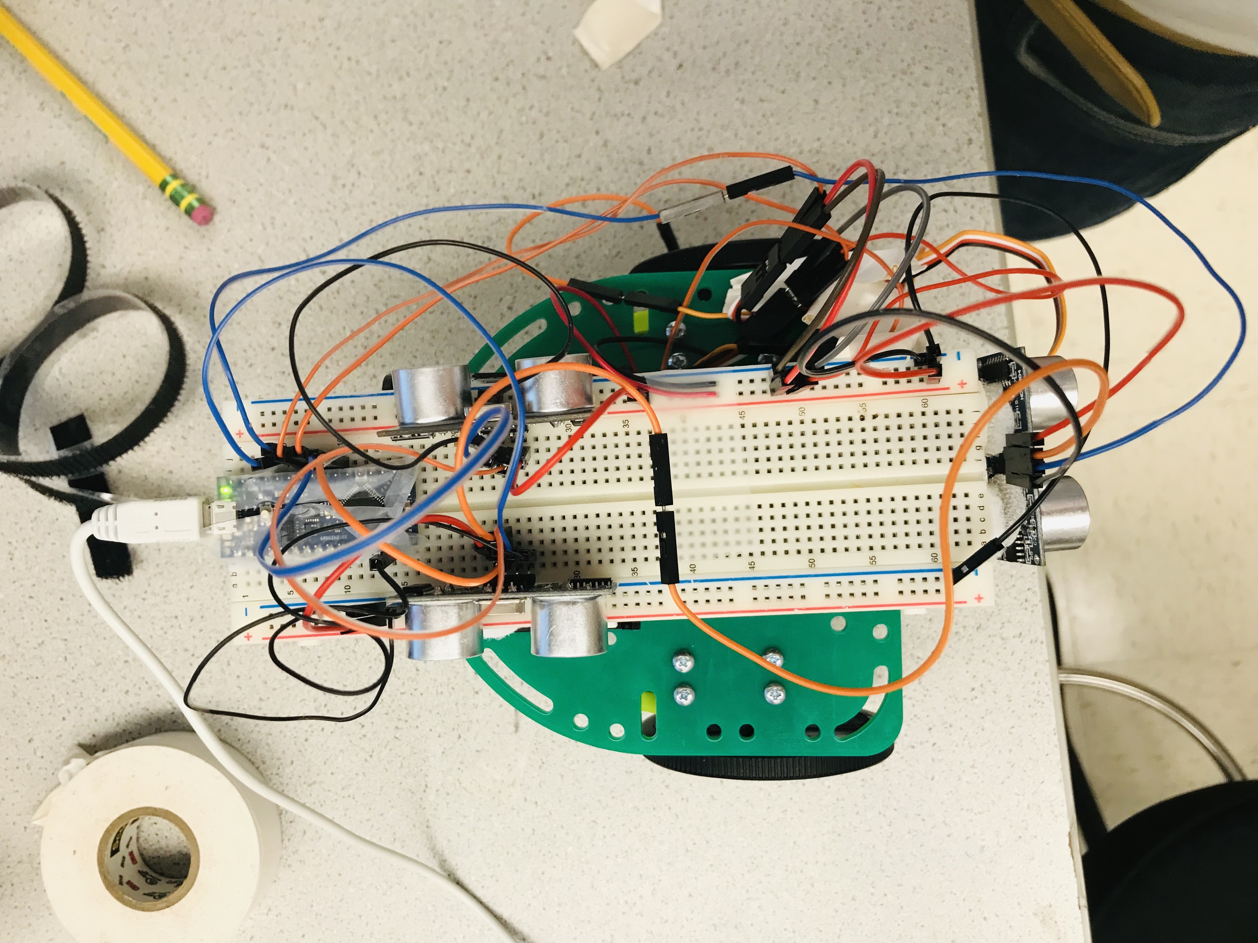
The US sensors were connected to the digital ports on the arduino, with the triggers connected and each echo pin connected to a pin on the arduino.
The sensors were testing using code that would display the reading of the US sensor to the serial monitor, distance of a surface from the sensor. After we made sure that the sensors were connected and worked as desired, we moved on to the final demo. For the final demo, we were tasked with navigating through a simple maze, and output a certain string at each turn which displays its position, the direction it's facing, and readings off of each US sensor.
The code for the navigation was done in stages, with each stage advancing after a condition with the US sensor was met. For example, the robot was programmed to make the first turn to the left once the front US sensor reads 12 cm or less.
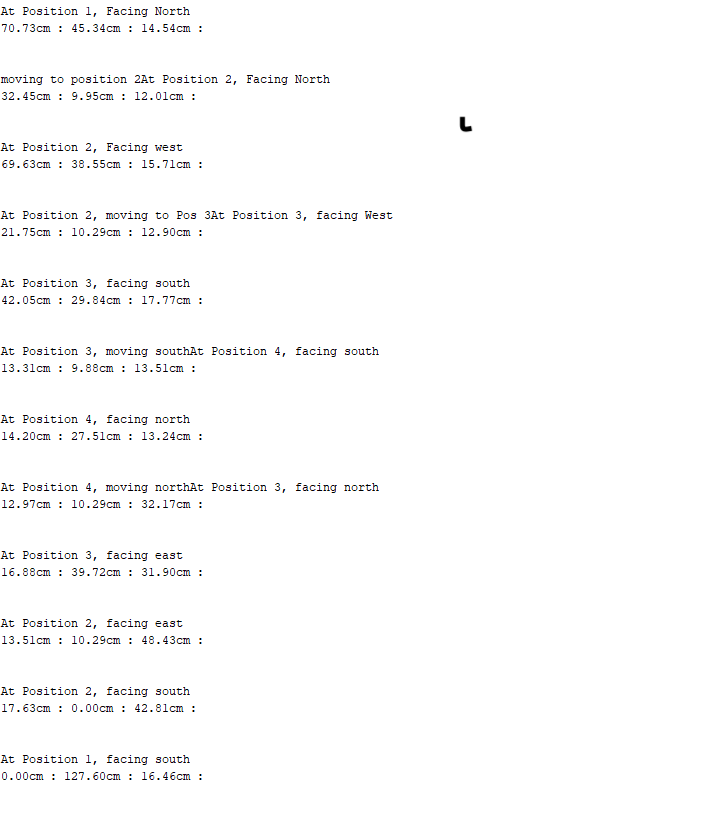
The following image is the output from the serial monitor after completing the maze.
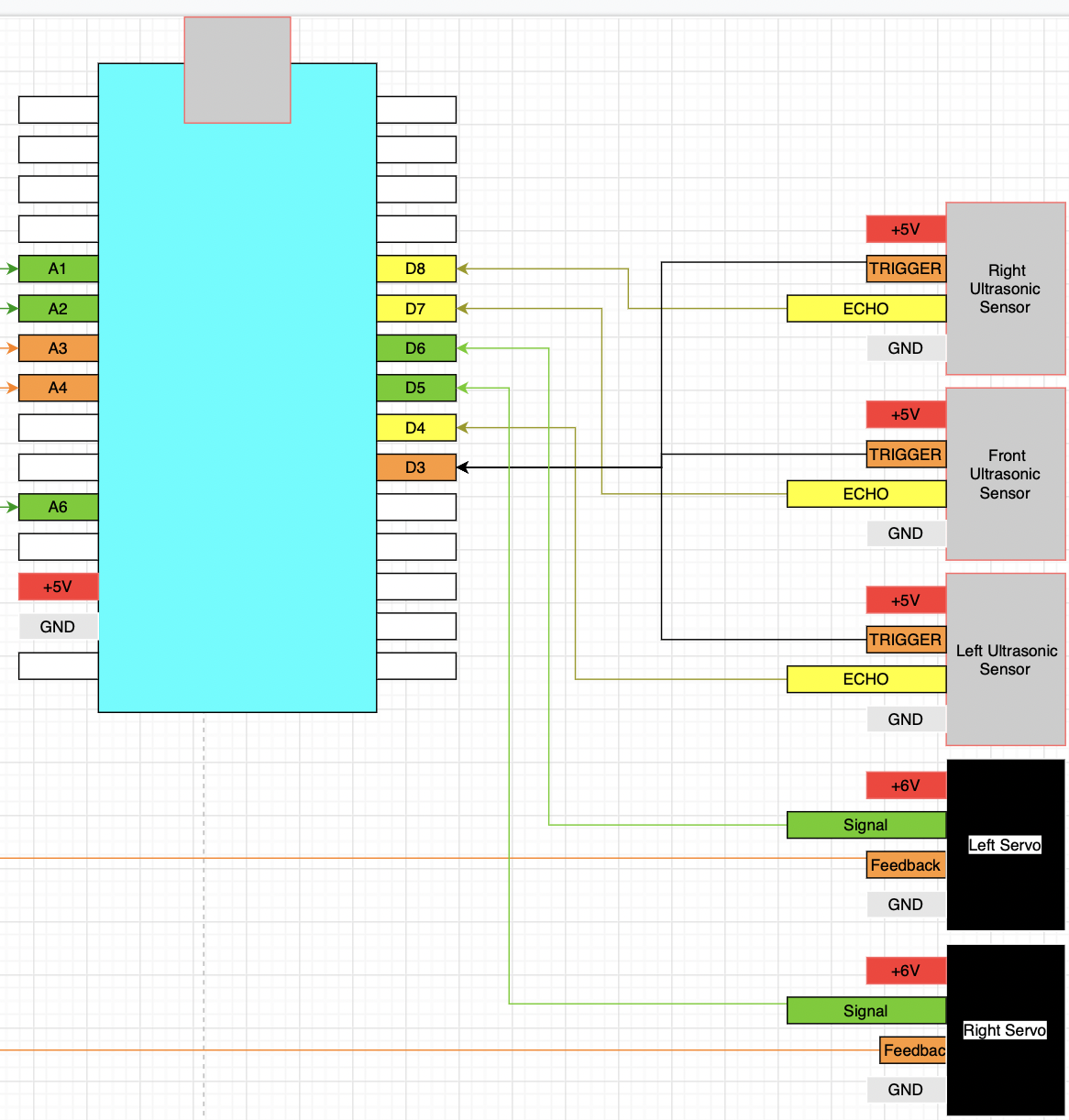
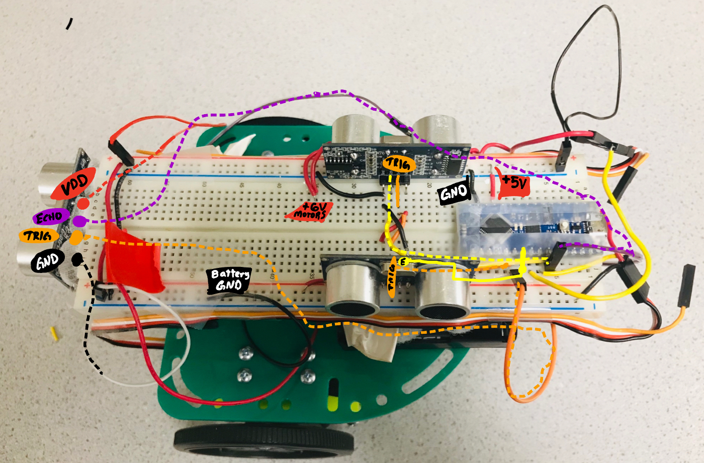
This was the final part of this lab. To prepare for the second part of the lab, the wiring was redone, made to be flat and easy to see and troubleshoot. Below is a diagram of the connections, as well as an annotated image of the robot laying out the connections.
To access different parts of the lab, use the links on the green bar on the top of the page. To return to the homepage, click "Home" at the bottom of the screen.