Summary: this part concerns the creation of the microphone circuit used to detect a certain auditory note. A circuit provides an amplified sound signal to the Arduino, which the Arduino processes in to a Fourier transform.
Mic Circuit and Testing
The signal from the microphone was passed through an amplifier to the Arduino.
Before starting the lab, a low-pass and a high-pass filter were simulated on LTSpice. From this we got a basic understanding of how a signal would react to these circuits. The cutoff frequencies for these filters are 1/RC radians, a fact important to making the microphone circuit work.
The basic microphone circuit was created first, which would pass an unamplified voice signal to the Arduino. The microphone was connected via a high pass filter where the resistor was connected to ground.
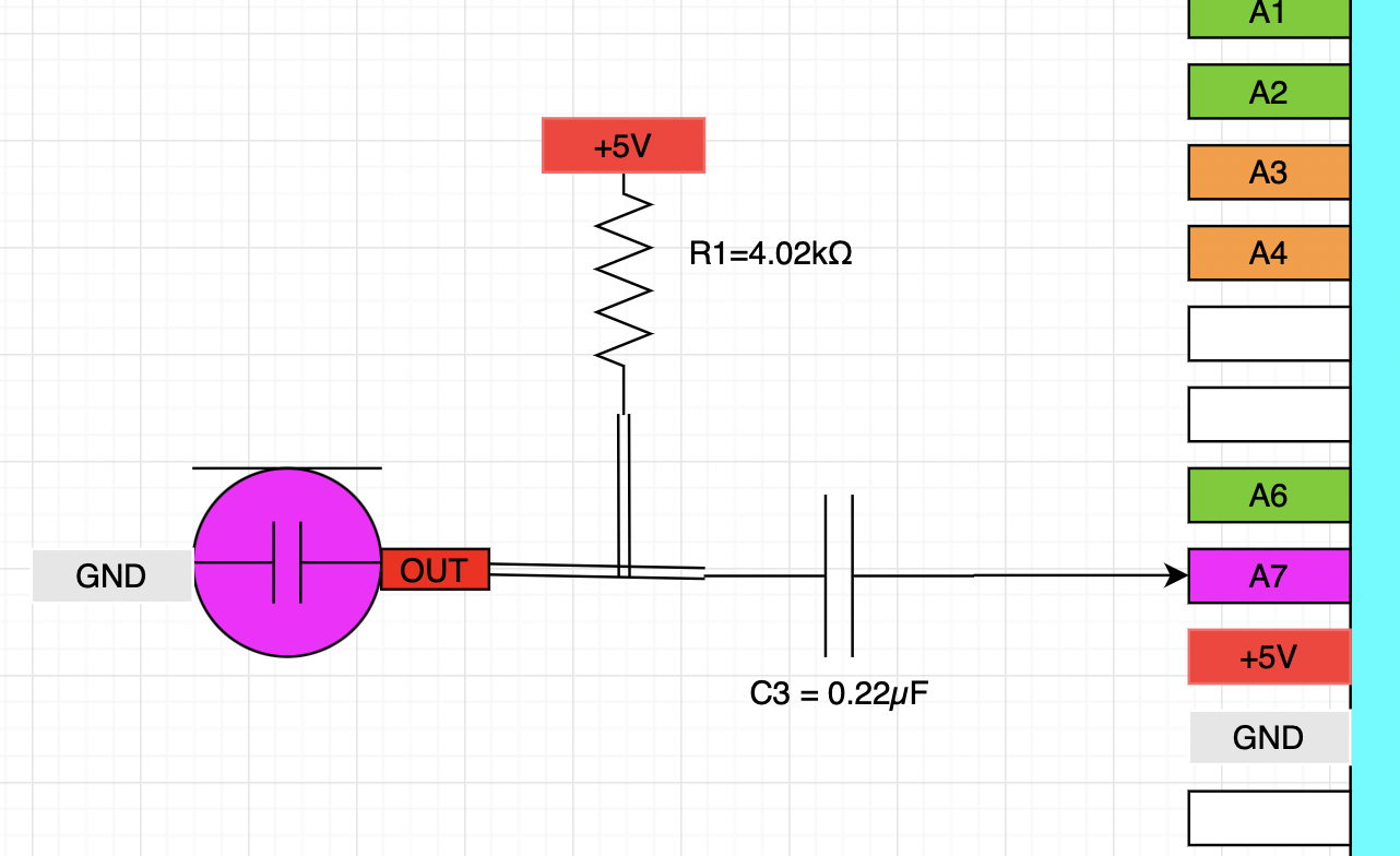
This circuit was then tested with Matlab, where the data was taken on the Arduino then sent to the computer for analysis. The data was as expected, and a plot of the time-series data and Fourier transform are shown below.
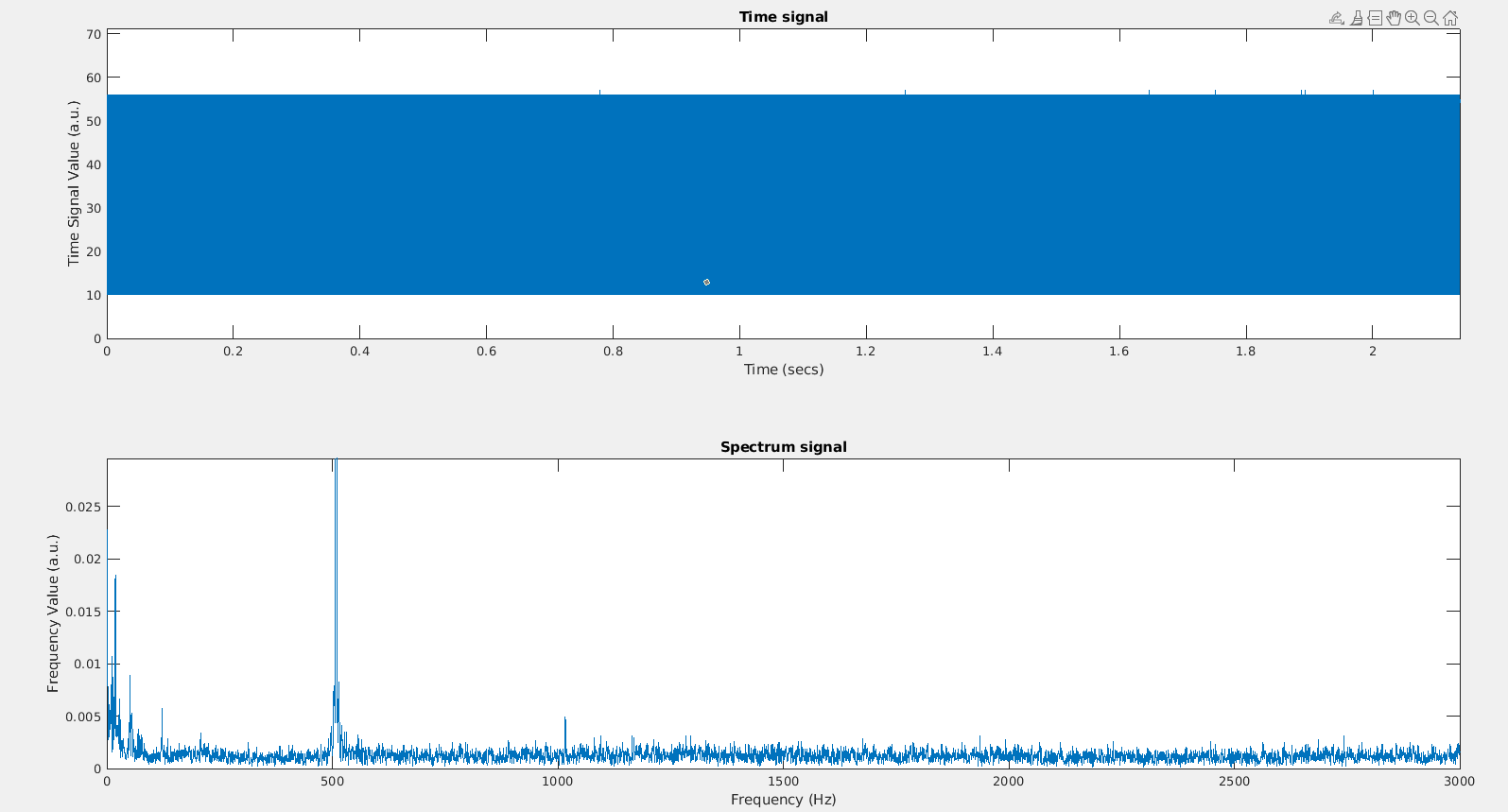
The signal from this circuit had a weak amplitude. To increase the signal strength, the signal was passed through an amplification circuit to the Arduino.
Amplification
A circuit was built that would increase the amplitude of the signal enterred on the Arduino.
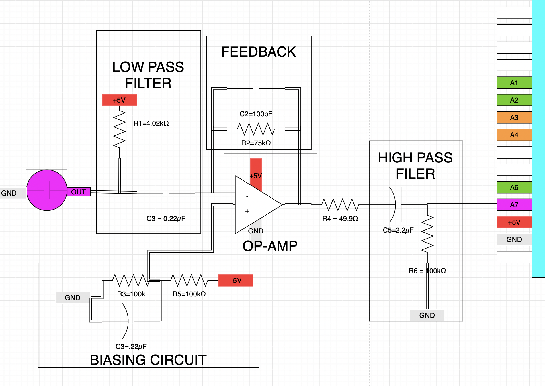
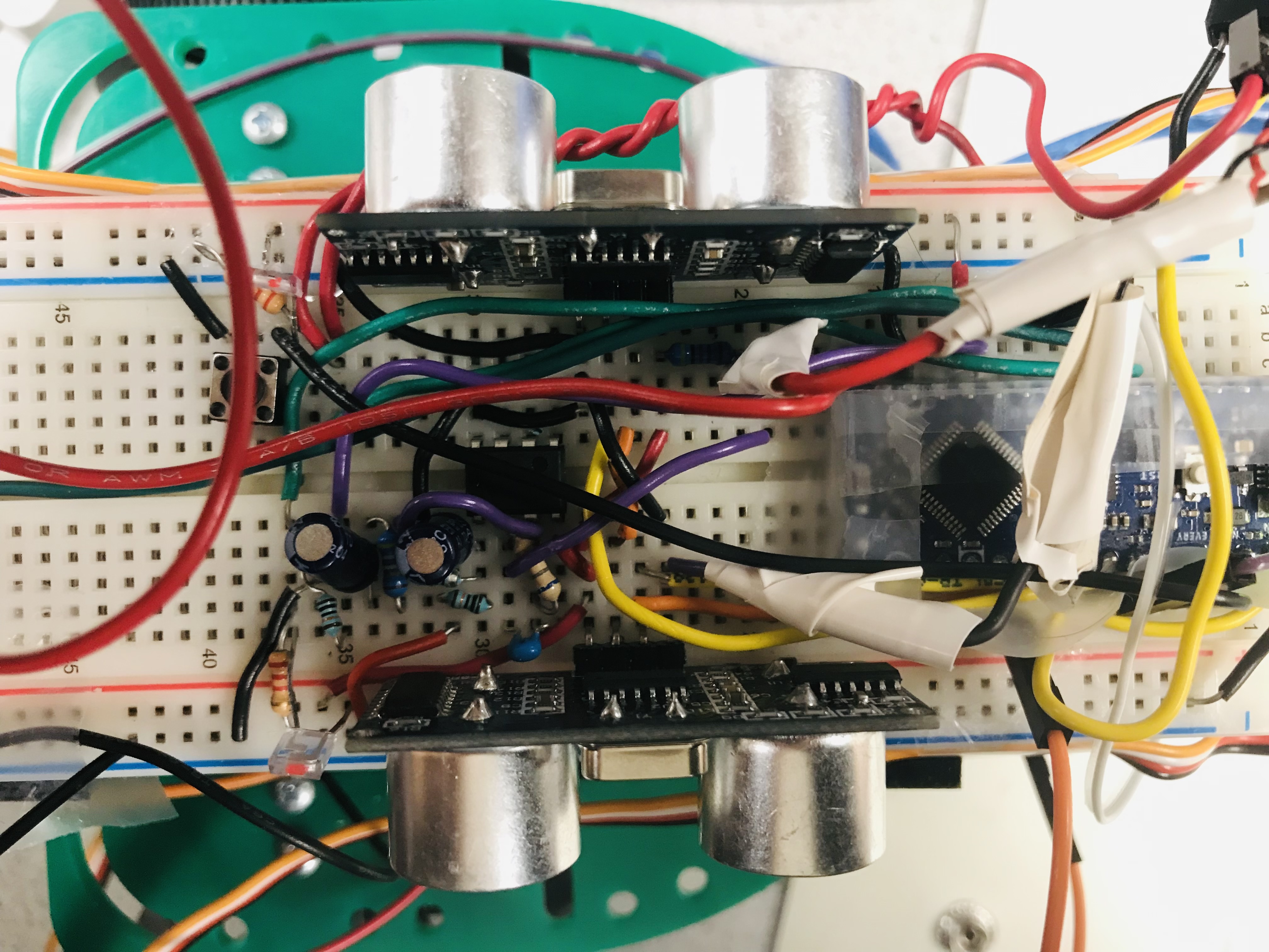
The circuit was built on the Arduino and tested on the oscilloscope to make sure it was properly installed.
The Arduino measurements when listening to a 500Hz signal were plotted in an identical matter as before, yielding the following time-series data and Fourier transform plots.
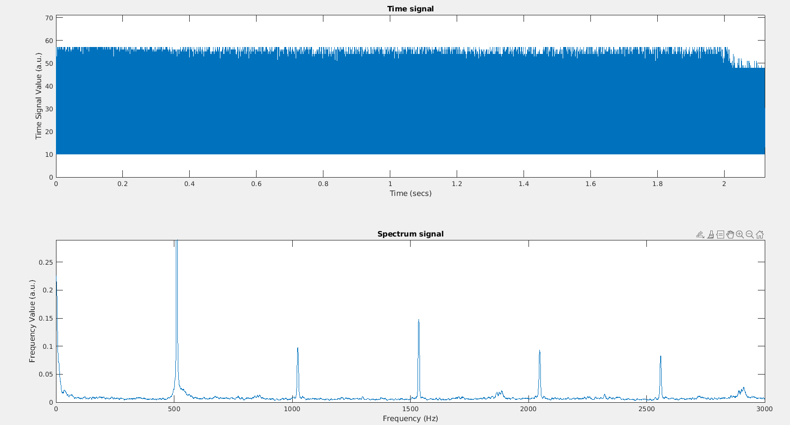
From this, it was determined that the physical circuit was working as designed, as the amplitude at the peak at 500Hz was ten times higher than when it was unamplified. We then needed to program the Arduino to be able to the Fourier transform on-board, so that it can work while disconnected from the computer.
Fourier Transformation on the Arduino
The Arduino was coded to be able to complete the fourier transformation locally.
We used the prewritten library FFT to program the onboard Fourier transform. We also modified our code to use interrupts to measure data, rather than determining when using ADC flags to determine when it was done. The counter (TCA) was set to run an interrupt service routine every 0.4366ms, which would take time domain data. After enough data was taken, the data was formatted to be used with pre-written functions in the FFT library to perform the fourier transform. This result was put in an array that was subsequently printed to the serial port so that the results could be checked.
We tested the results from the Arduino using 3 different frequencies, and plotting the output given by the Arduino.
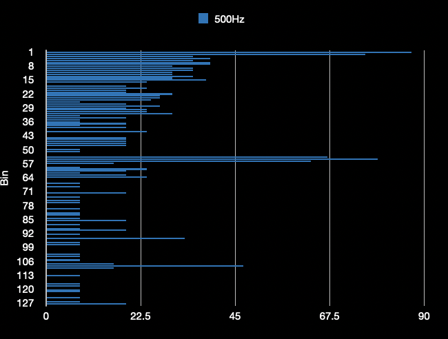
Above is @500Hz.
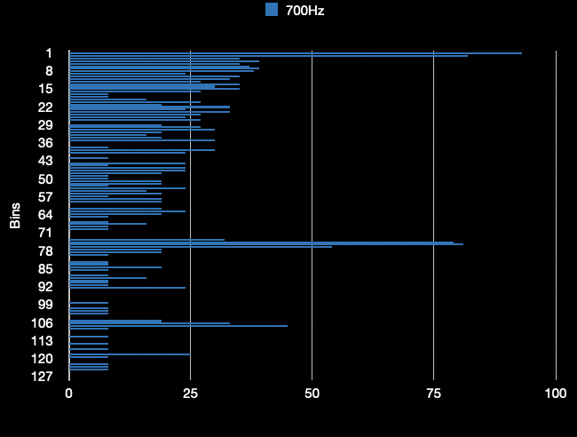
Above is @700Hz.
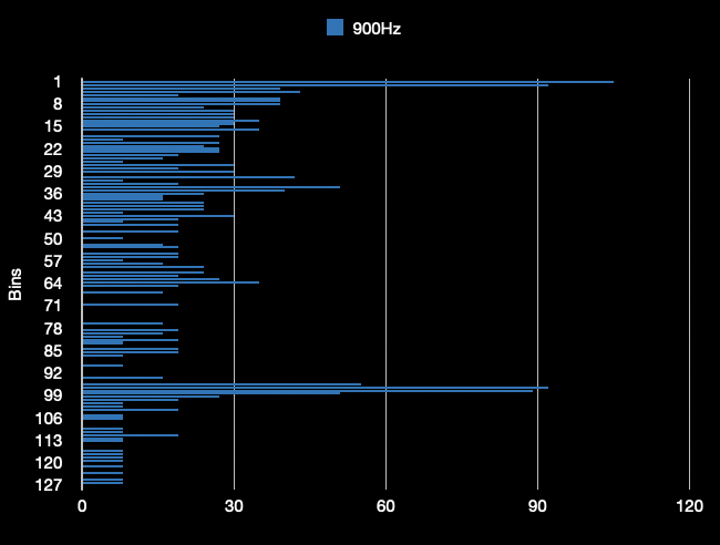
Above is @900Hz.
The above results were as expected, with a sharp peak at the bins corresponding to each respective frequency. Significant noise is present in the signal, but that is expected with this circuit, since any noise in the circuit was amplified along with the signal. For the final project, it will be simple to measure the height of the bins corresponding to the musical note to determine when the note is played.
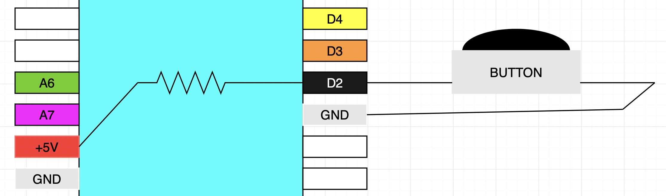
Override Button
A simple circuit was created that would be pressed if the Arduino failed to detect the signal.
A pin on the Arduino was dedicated to detected when an override button is pushed, which will work as a fail-safe in case the Arduino is unable to detect a particular note. A pull-upcircuit was used to accomplish this, using a built-in pull-up resistor in the Arduino. The code was tested using the LED on the Arduino, and all was good in the hood.
To access different parts of the lab, use the links on the green bar on the top of the page. To return to the homepage, click "Home" at the bottom of the screen