Summary: this part is about putting it all together, programming the robot to complete the maze, find and measure the treasures, start on the 440Hz note, and moving straight through the maze.
Radio transciever
Being able to display a number from the robot onto the base station
The purpose of the base station is to display an arbitrary number sent to it by the robot. To do this, a pair of radio trancievers were used on the base station and the robot using the MISO/MOSI/SCK/CE/CS pins on each respective Arduino. An RF library was used that had pre-written functions for controlling the radio. We simply chose the RF bands the radios operated at and modified the number of attempts the radio would make until it got an acknowledgement packet. This code was adapted into the seven segment display code written in lab 2, making it so that any integer recieved would be displayed on the board until another integer was recieved.
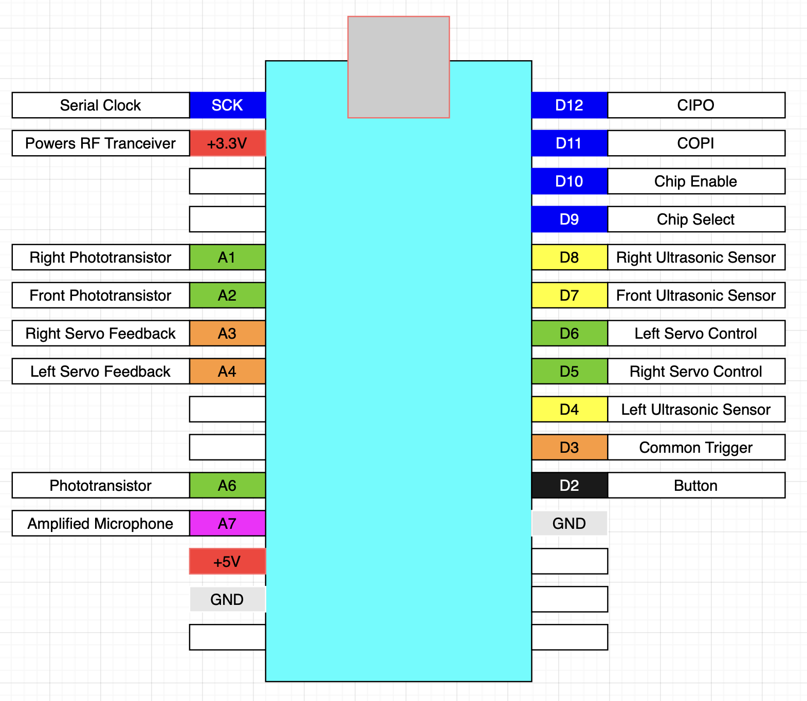
This was the last peripheral to be added to the robot, so the final diagram for the way we used the Arduino pins is given above.
FFT
Being able to detect an audio frequency
The robot was meant to stay still until a 440Hz note was heard on the microphone. The code written for Lab 3 simply found the FFT and printed the results. This code was adapted in the following way:
- Remove the code printing the results of the FFT
- Run the code on a loop on the condition that the note hasn't been found.
- Determine when the note has been found by taking the amplitude of the bin corresponding to the 440Hz note.
The following is a graph of the FFT when a 440 Hz note is played. It can be seen that bins 47, 48, and 49 contain the main peak, while there are harmonics corresponding to where 880, 1320, etc. frequencies are.
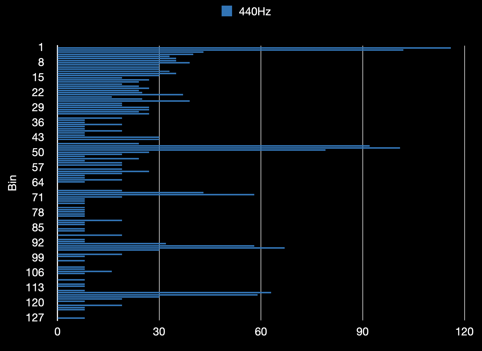
Below is a zoomed in portion of the graph at the frequencies of interest.
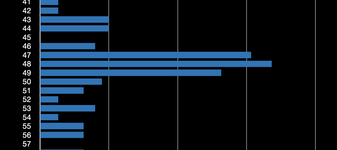
From trial and error, we found that the note has been found when the amplitude of the 47th bin exceeds about 45 on our robot. Setting it much lower than this makes the robot too sensistive to noise, and setting it higher reduces the probability of triggering the sound.
Navigation and Movement
Programming the robot to know where to go and how to go.
This section is composed of two parts: one concerns the physical movement of the robot and the other about the algorithm for determining where to go.
First is the movement of the robot. Distances were determined using servo feedback, including turns. Through testing we found that a decent level of accuracy can be achieved with a combination of two methods. First we calculate the number of "ticks" to move the robot. We then subtract from this "goal" the difference in the servo feedback until it becomes 0. This assumes a monotionically increasing/decreasing servo feedback, except for the "rollover", which can be constructed mathematically by keeping track of the "maximum" feedback and resetting it after a certain point. The math is reversed when the servo is moving in the opposite direction. To increase accuracy, for the last 50 "ticks" or so, the servo is stopped when the servo feedback equals current feedback + goal, while continuing with the first method to avoid rollover if necessary.
After writing the servo movement code, we wrote the navigation code. We used Carl's DFS algorithm, which meant keeping track of a frontier set of unsearched nodes, and a visited stack, which is a list of nodes in the order they were visited. Whether a node should be added to the frontier set was based on the distance read by the ultrasonic sensor.
PID control
Keeping the robot moving straight along the maze.
PID control was done using the left/right ultrasonic sensors during forward motion of the robot. We found that a lightly modified version of PID was effective in keeping the robot moving straight in a 15 inch wide corridor. The "error" was taken as the difference between the distance measured by the ultrasonic sensors. In addition to this, another term was added to the "P" with its own associated constant k_p_2, which was the difference in the right ultrasonic sensor readings in two points in time. We found this effective when the robot was moving through a 15" wide hallway.
- left = distance measured by left sensor.
- right = distance measured by right sensor.
- diff = right - left
- timediff = right - (previous value of right)
- PID = diff*k_p + diff*k_i*(elapsed_time) + timediff*k_p_2)
The result of the PID formula was used to control the speed of the servo motors. For example, if the result of the PID was 20, the difference in magnitude of the servo speeds would be increased to 20 (magnitude = difference from 90). PID adjustments are meant to be reset whenever a significant change in a sensor reading occurs, meaning the sensors are in front of a new gap/new blocking wall in front of them.
Frequency measurement
Being able to read the treasure if the robot is by the blinking light,
The code from Part 2 that read the phototransistors required some modification for the final demo:
- Reset the control registers back to initial settings for TCB, otherwise the counter that millis() returns won't count.
- Each phototransistor would be measured in order until a frequency is measured.
- 20 measurements are taken from each phototransistor.
- A nonzero (greater than 10Hz) frequency indicates that a light is present. The median of the nonzero data is taken to be the desired frequency.
It was determined that the blinking light could be detected with reliability if the robot waited 3 seconds at each node of the maze, and during those 3 seconds run the frequency detecting code on loop. This led to an issue during the final lab which will be explained in the next section.
Final demo performance
Where the robot failed
The robot ended up failing on navigation and getting points off for using the microphone override. Frequency measurement and display was performed fine when the robot was held directly to the treasure. The following attempt is the first, where the FFT was used to determine the start postiion. Due to an oversight in the code, the robot is designed to start motion 3 seconds after hearing the note. This is due to the robot taking 3 seconds to check each node for a treasure, and also checking the starting node, since the treasure couldn't have been assumed not to be at the start.
It can be observed that, given the oversight, the robot detected the note at the correct time and started 3 seconds later. The following was another attempt at the maze where the override button was used.
In an unshown attempt, the robot moves prematurely, before the note is played. This was likely due to the mic picking up noise right after the calibration, where the wheels are moved 100cm to detect where the maximum feedback value is. Like the previous trial, the robot fails to move through the maze. It doesn't move straight along the walls, since PID was not programmed to kick in until the robot moves in a 15" hallway. Also, the robot fails to detect the empty node in the same position, two nodes left of the start. This is probably due to the robot failing to add this node to the frontier set for some reason. Lastly, this last attempt was done to get extra footage. The robot is seen to move fairly accurately, but still fails to detect the empty node.
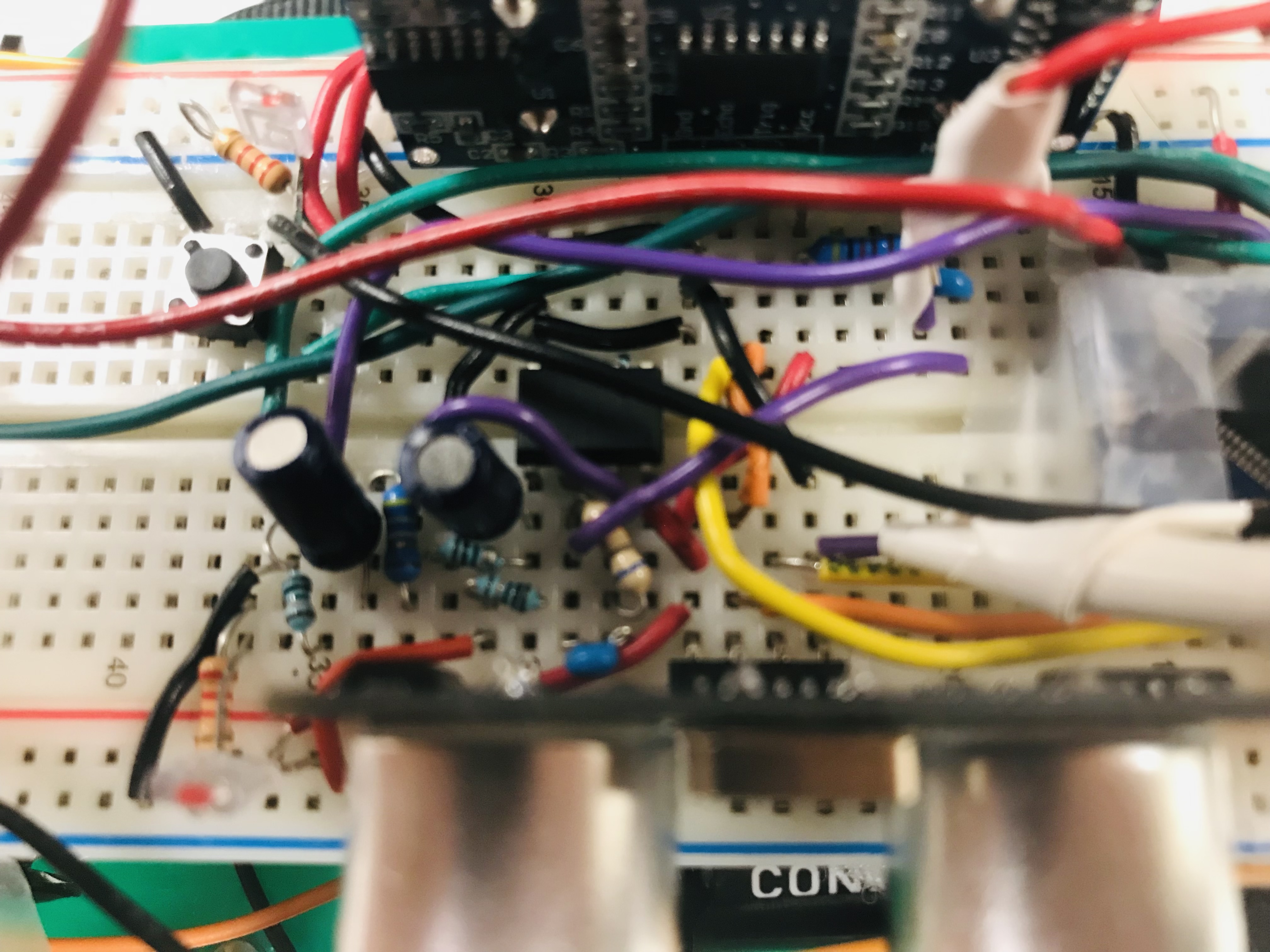
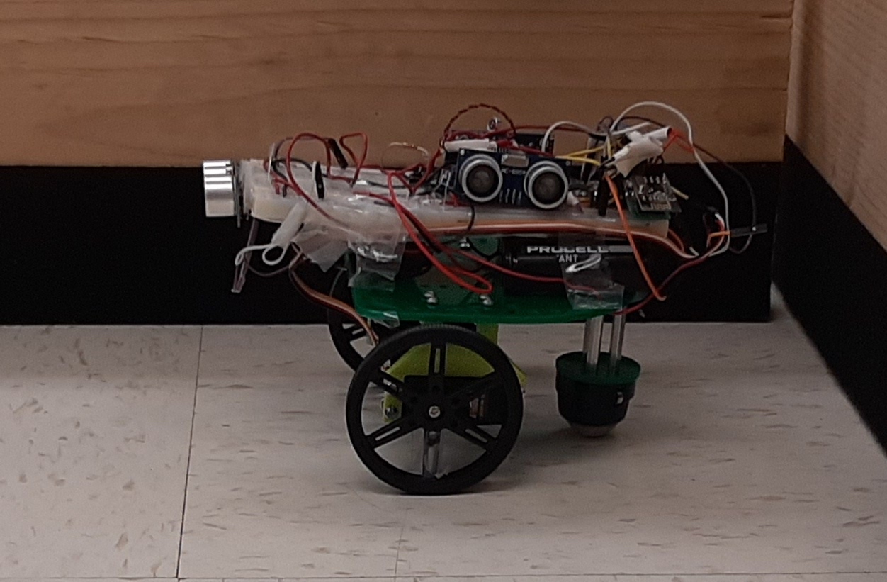
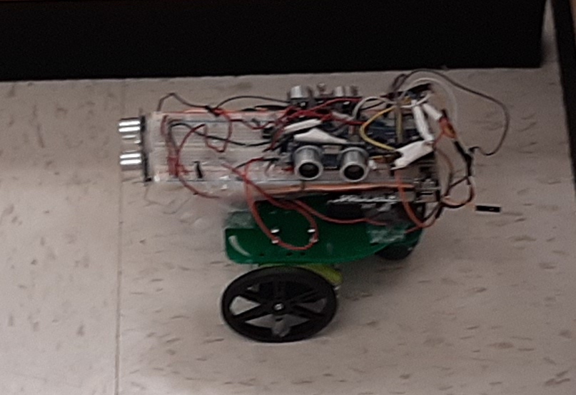
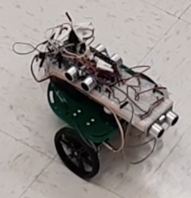
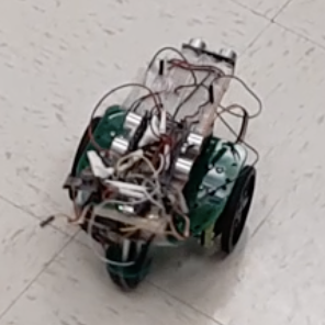
Here are some images of the robot, showcasing the wiring that was done. The following is a close up of the top of the Arduino, containing the mic amplification circuit and the ultrasonic sensor wiring.
To conclude, I'll say that the development of this robot was incredibly educational in how to do an engineering project in general. Organizing what work is done, delegating with Schuyler, and troubleshooting this robot was good practice for a future engineering project.
To whoever is reading this site, thank you very much for reading all this, and keep up the good work!
-Ignacio Romo '24, 12-8-2022
To access different parts of the lab, use the links on the green bar on the top of the page. To return to the homepage, click "Home" at the bottom of the screen