Objectives
- Get familiarized with the Arduino software
- Demonstrate proper movements with servo motors
- Successfully gather and interpret data from ultrasonic sensors
- Code the Arduino and robot to navigate through a simple obstacle course
Materials
- Robot frame
- 2x servo motors
- Ball caster wheel
- Array of screws, nuts, and washers
- Arduino Nano Every microcontroller
- 3x ultrasonic sensors
- Breadboard and wires
Setting Up The Robot Frame and Arduino
During the first part of the lab, we focused on setting up the robot and getting familiarized with the Arduino software. Constructing the frame of the robot was straightforward. We installed the two servo motors onto the back of the robot frame while installing a ball on the front, so the robot can pivot easily. Next, we secured a 9V battery and a 4.5V battery pack to the top of the robot using velcro. In the future, the 9V battery will power the Arduino, and, subsequently, all other electronic components, and the 4.5V battery pack will exclusively supply power to the servo motors. We then placed a breadboard on the batteries, again using velcro strips. This completed the robot frame, so, next, we needed to understand the Arduino IDE software and functionality. Simply put, we learned how to compile code, upload code to the actual Arduino, and bring up the serial monitor in order to read print statements. To make sure we understood the basic functionality of Arduino coding, we performed a basic exercise using the onboard LED. We showed that we were proficient in understanding what the purposes of the two main sections of code--setup and loop--were, and were able to demonstrate the LED blinking at several different frequencies. In this project, we are using an Arduino Nano Every, so after we placed it into the breadboard, we scanned over the pinout of the microcontroller, the pins we will be using, and their functionality in this context.
Working With The Servos
In this next section of the lab, we were tasked to demonstrate proficiency in understanding how servos worked and how to code them in order to complete basic movements. In order to begin, we had to download and update the Servo.h library, so we would have the functions necessary to make the servos turn when certain values were inputted. We used pins D5 and D6 to control the left and right servo motors respectively. Additionally, before we could begin experimenting with the values to make the robot move, we had to adjust the potentiometer to calibrate the servos, so when a 90 value is written to the servo, it does not move. Once that was complete, we tested the servos with various input speeds at different times, so we would know how to perform movements such as 90 and 180 degree turns. Some difficulties arose during this part because the servos were inconsistent. For example, our robot always moved slightly to the right even when calibrated perfectly and the same respective values were written to servos (i.e. 120 and 60 were written to the left and right servo respectively). Even more so, we had problems with the turns themselves. Even after consecutive tries with the same values, the turns were not the same. This could be attributed to the quality of the servos themselves, the ball caster wheel, and/or the servo wheels slipping on the surface. However, in the future, we will write algorithms based on ultrasonic sensors to make our turns and keep the robot straight. Ultimately, we were able to complete the servo demo. We were successfully able to move the robot straight for approximately 20 centimeters, turn right 90 degrees in place, turn left 270 degrees in place, and, finally, return to its starting position where it completed a final 180 degree turn to the right. This is shown in the video below.
Measuring Distances Using Ultrasonic Sensors
Next, we were tasked with connecting the ultrasonic sensors to our robot and the Arduino. We did this by securing three ultrasonic sensors to the body of the
robot, one in the front and two on either side. When it came down to wiring the ultrasonic sensors to the Arduino, a problem arose. Each of the three sensors
have a trigger and echo pin, where the trigger pin receives a sign from the Arduino to send a pulse out and the echo pin detects a signal from the reflected trigger
pulse and informs the Arduino. Wiring all six echo pins to six individual pins on the Arduino would exhaust all of the digital pins before we reach the final design
of the robot. To solve this problem, we simply tied all of the trigger pins together, while leaving all of the echo pins separated. We used pins D3 for all the
triggers, and D4, D7, and D8 for the left, forward and right echo pins respectively. After completely wiring the ultrasonic sensors, we downloaded the script that
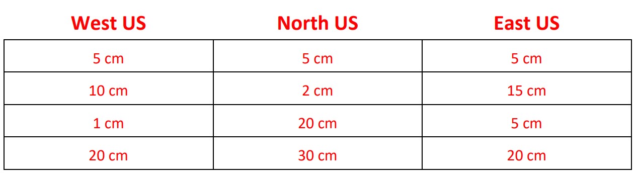
calculated distances based on the sensors, and wevchecked the serial monitor to confirm accurate readings. The cases we tested for are shown below.
Navigation Using Ultrasonic Sensors
Our final challenge for this lab was successfully navigating through a simple obstacle course, which is shown and specified below.
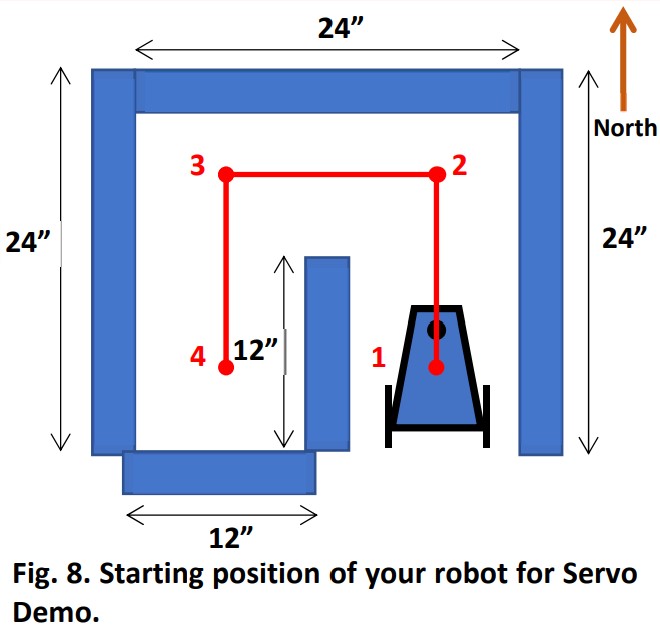
Our navigating robot must do the following:
- Start in position 1, immobile.
- Once the RESET button is pressed, it will remain motionless for one second, then head North towards position 2.
- Once at position 2, it will turn smoothly in place to its left to face West, then navigate towards position 3.
- Once at position 3, it will turn smoothly in place to its left to face South, then navigate towards position 4.
- Once at position 4, it will turn smoothly in place to its right to face North, then navigate towards position 3.
- Once at position 3, it will turn smoothly in place to its right to face East, then navigate towards position 2.
- Once at position 2, it will turn smoothly in place to its right to face South, then navigate towards position 1.
- Once at position 1, it will turn smoothly in place to its left 540 degrees ending facing North where it will remain stationary.
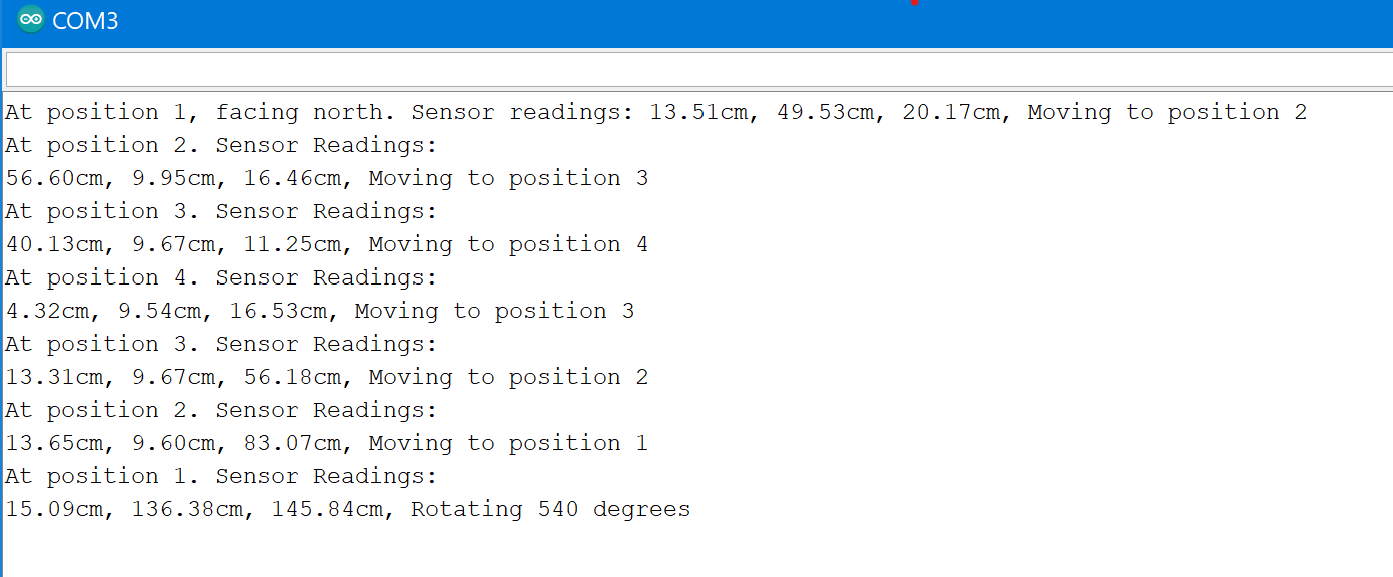
We implemented this by coding a finite state machine which, based on its ultrasonic sensor measurements and its previous position, would rotate the appropriate amount to face the direction it needed to head. Ultimately, this implementation was successful, but it was subject to issues that needed to be addressed. One recurring problem was that of the inconsistency of the turns and forward movements. This could be attributed to many issues mentioned above, such as the quality of the servos themselves, the ball caster wheel, and/or the servo wheels slipping on the surface. These issues were resolved in the same aforementioned ways. Another major problem was that of the loop structure. Initially, multiple case statements were skipped because the ultrasonic sensors were not recalibrated and still had the values measuring a wall ahead, causing the robot to execute two turns when it only should have been completing one. We solved this by stopping the robot based on millis (the eternal clock value on the Arduino) and pausing for a time until the ultrasonic sensors received new data. The resolution eliminated the problem of executing two movements consecutively. Below is a video of our robot successfully navigating through the obstacle course, accompanied by the serial monitor print statements of that run.
Gallery
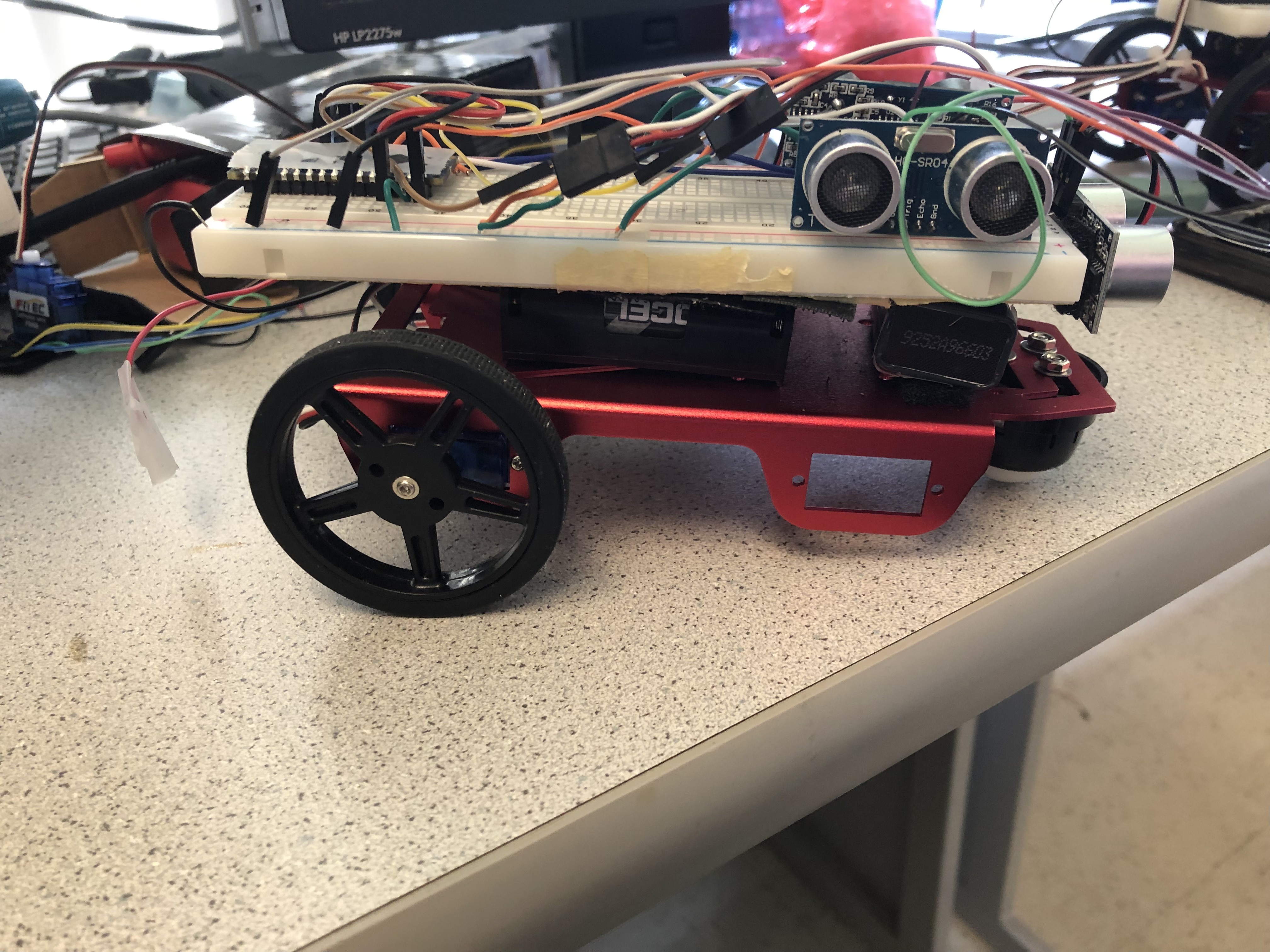
Above is a photo of our robot from the side.
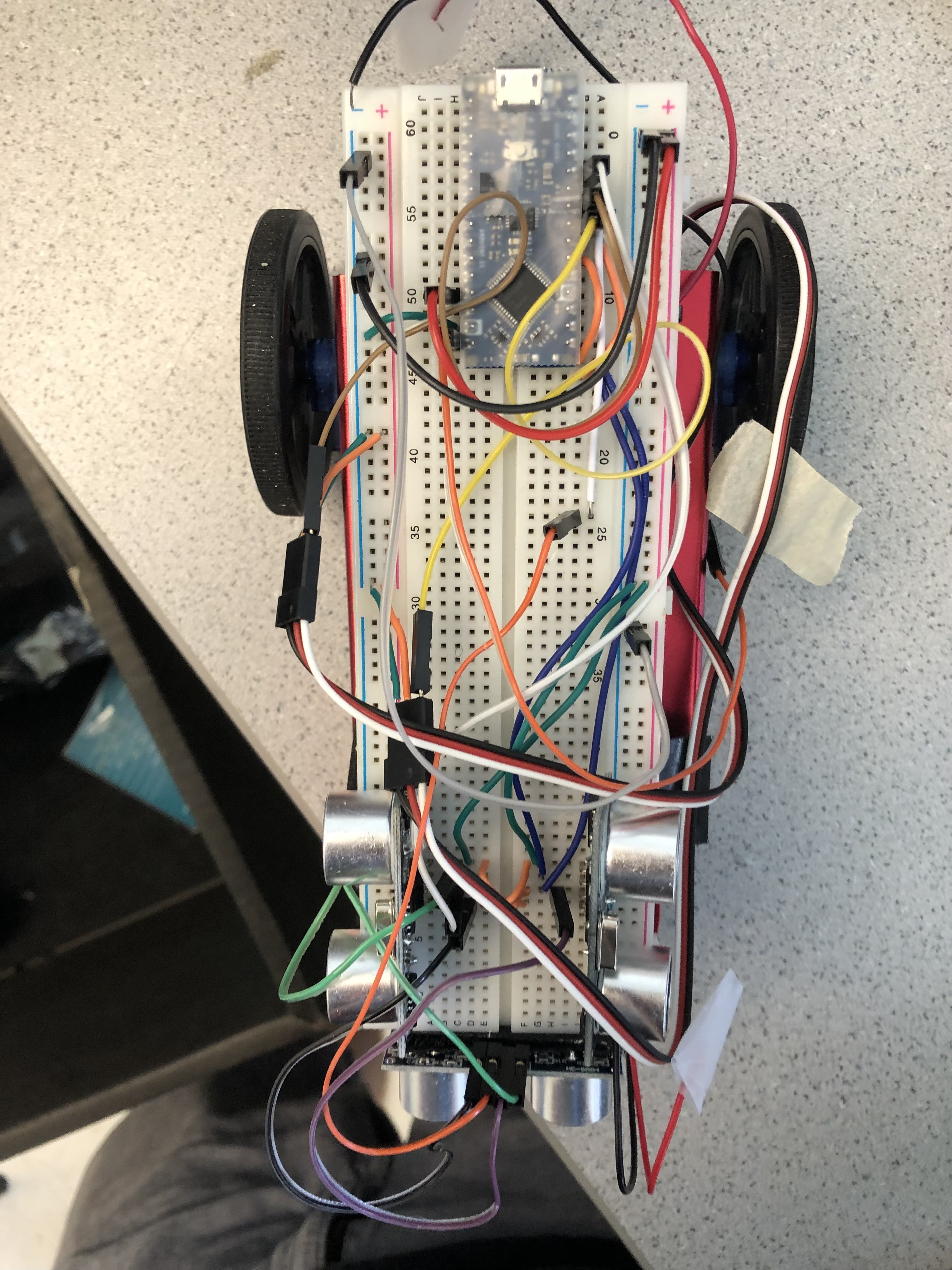
Above is a photo of our robot from the top.