Objectives
- Solder PCB RF Adapters
- Implement a RF transceiver to the robot and base station
- Build a pushputton cicuit
- Code PID control and navigation algorithm
- Finalize robot for final demo
Materials
- Robot
- Wires and resistors
- 2x PCB RF adaptor chips
- 2x 4-pin headers and 2x 3-pin headers
- 2x 8-pin header recepticles
- 2x RF transceivers
- Soldering gun
- 1x pushbutton
Implementing RF Transceivers
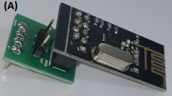
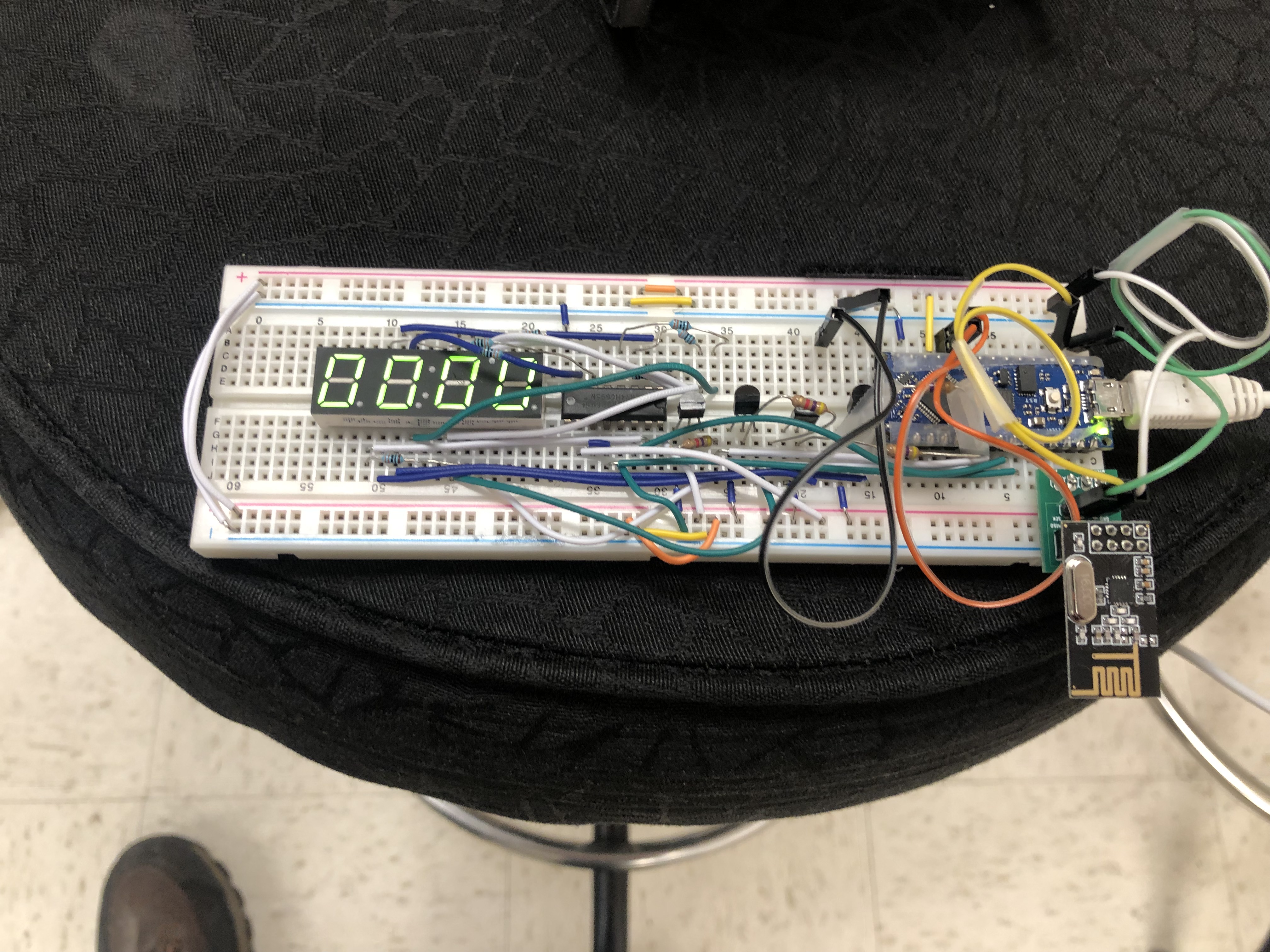
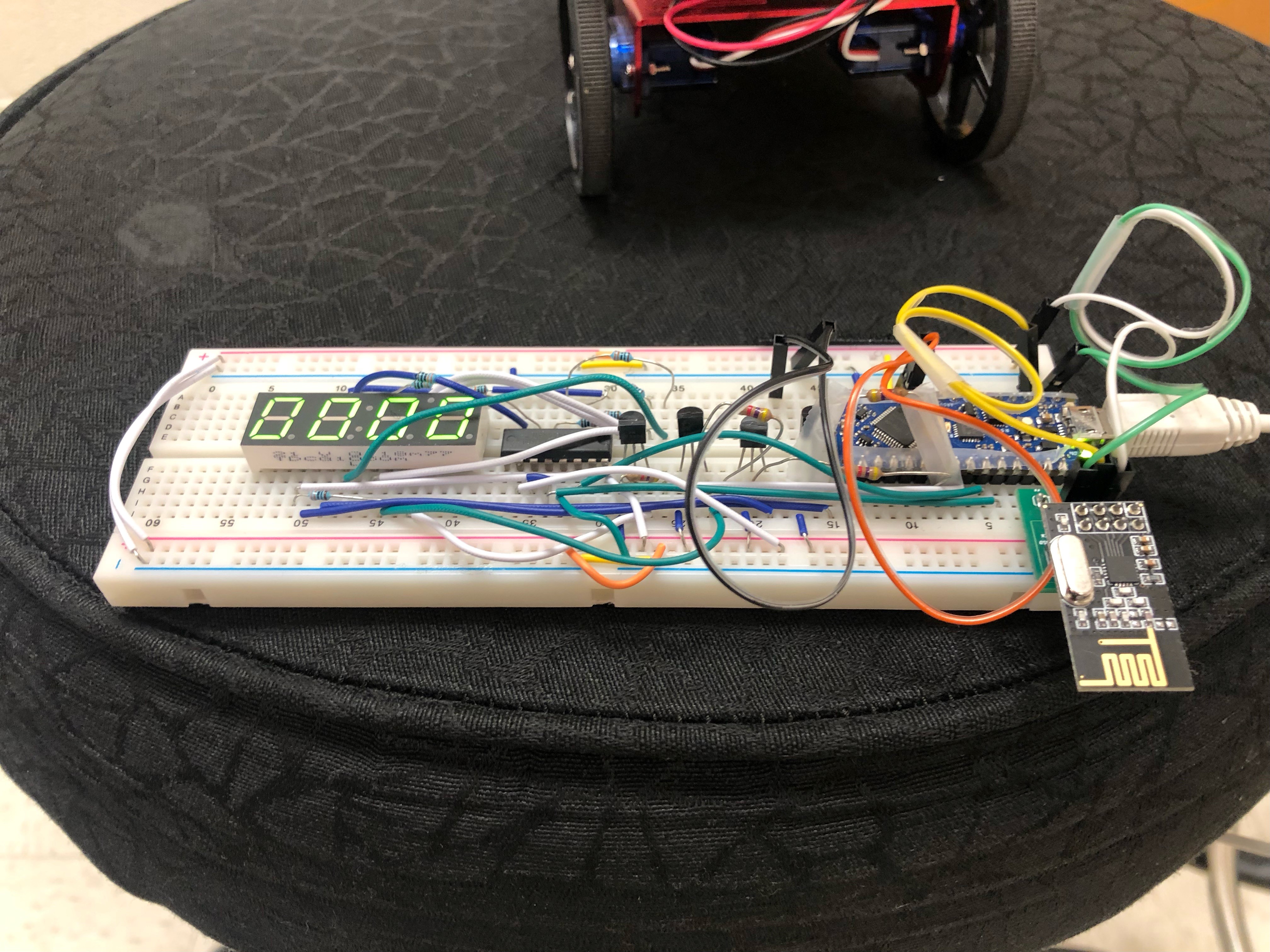
The purpose of having RC transceivers is so that the robot can communicate the detected frequencies to the base station, which are then displayed on the seven segment display. The frequencies are detected from the phototransistor circuits developed in lab 2. Our first task of the lab was to solder an adaptor, so the RF transceiver could easily interface with the breadboard on the robot and base station. The RF transceiver and adapter is displayed below.
Once the RF transceiver was properly wired to the arduino and base station, our next goal was to set up a radio library, provided by Arduino and establish a distinct channel, so our robot's communication does not pick up interference from other students' RF transceivers. After some testing, everything was working properly.
PID Control and Navigation
We implemented a PID control so that the robot can stay centered between two walls or stay a certain distance from one wall. We opted to only use the proportional and derivative terms of the PID function because after rigorous experimentation with values of each term, we noticed the integral term had little to no effect or totally ruined the straightening of the robot. Now that we were able to maneuver properly, we implemented a navigation algorithm. Our algorithm would be a very simple right wall follow algorithm. Simply put, the robot will stay a certain distance from the right wall at all points and make appropriate turns when necessary. Our code prioritized turning right, then going straight, then turning left, and finally turning around. Since we used right wall follow, we used the PID to stay a constant distance from the right when traveling straight. We created our own wait function, so that the ultrasonic sensors could be constantly updated and the frequency detection was constantly running, while the robot was executing its turns.
Finalization of Robot for Final Demo
Click here to view the full description of the final demo.For the finalization of the project, we combined all the work we've done over the semester in one file so that the robot could be successful. This included our Fourier analysis, frequency detection, and PID and navigation code. The Fourier analysis code would be executed on repeat until a threshold was reached indicating a 950Hz frequency was detected. Once detected, the robot would start to move, navigating the maze and searching for the two frequency treasures. A backup push button was installed so that if the Fourier analysis failed, we could manually start. Once moving, the robot would navigate autonomously, and once the treasures are detected and properly displayed to the base station, the robot will stop moving and end the demo. This is an oversimplified description, a lot of time was poured into debugging and altering previous versions of code, so that they can all work simultaneously in one file.
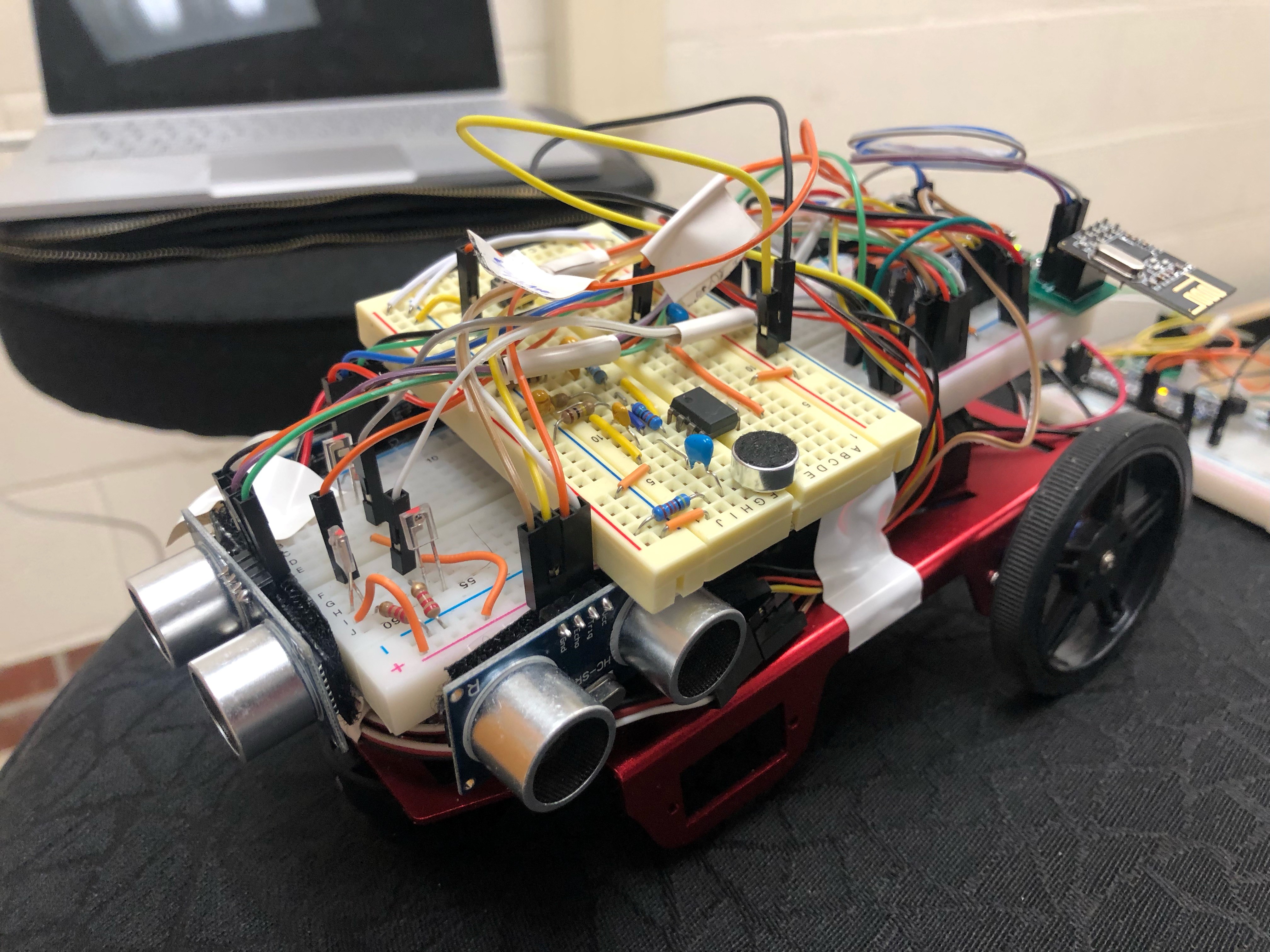
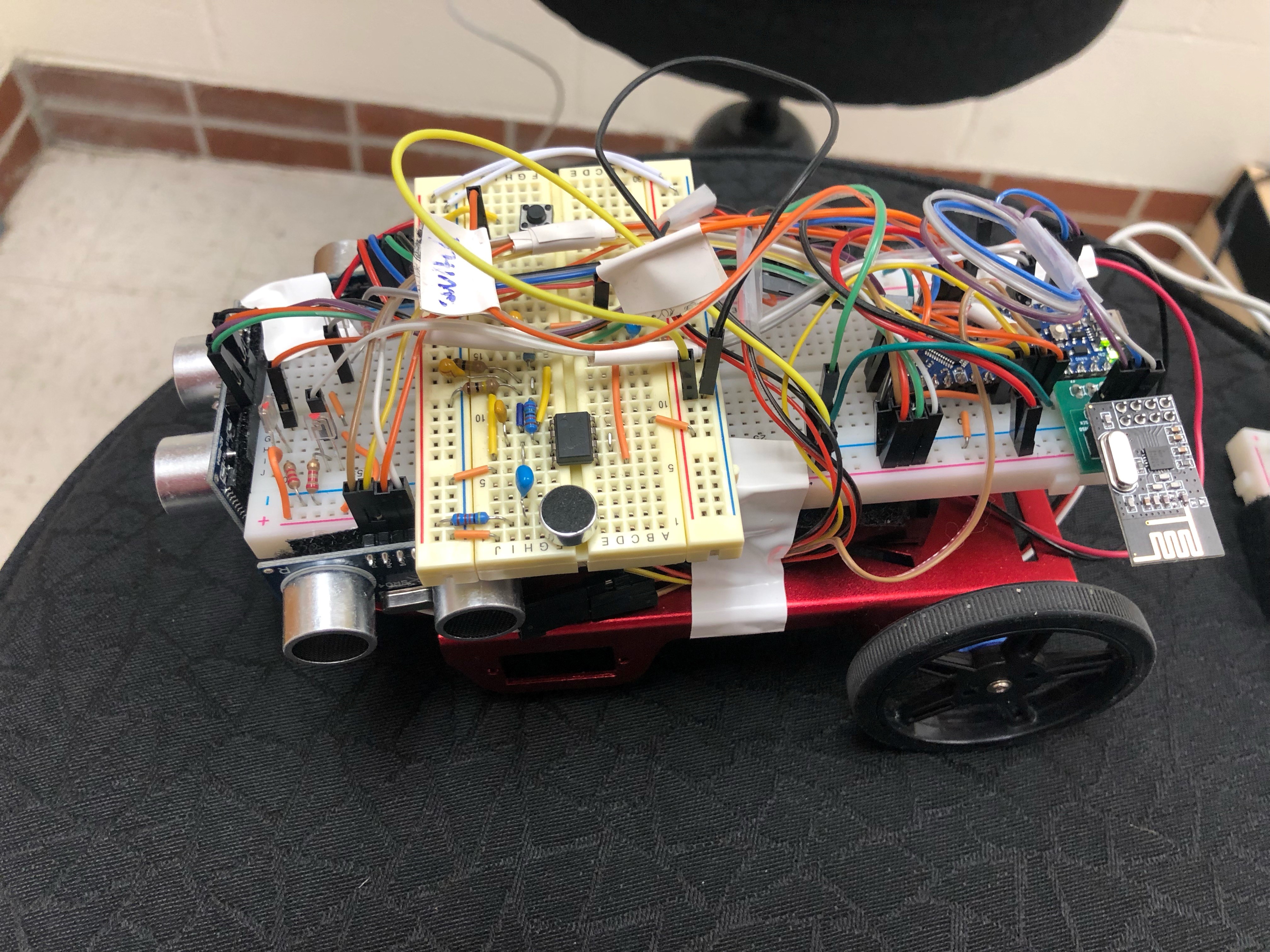
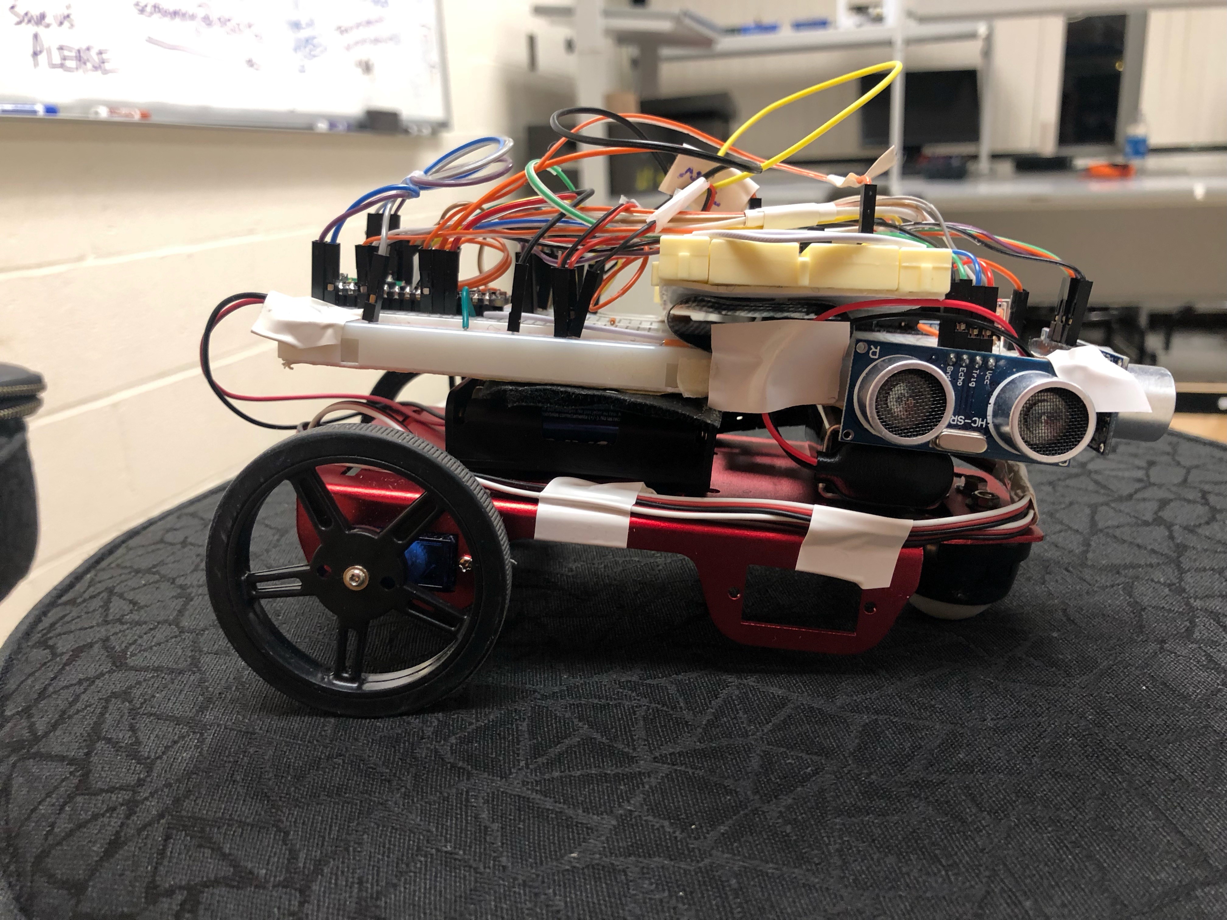
Final Robot Gallery
Video of Final Demo
Above is a runthrough of the final demo. Ultimately, the robot was successful in starting when the 950Hz was played, and though it was done off camera, detecting and displaying the two frequencies. The navigation and PID can be seen working properly for the most part. The few times the robot had to be adjusted was due to errors caused by the servo and ball caster wheel quality. For example, at 1:07, the robot skidded because the ball caster wheel got jammed, and at 0:22, the robot overshot the 180 degree turn while executing it perfectly at 1:05.