Objectives
- Build three IR light detection circuit with phototransistor on robot
- Build a simple IR light emitting circuit using the signal generator
- Test and characterize your IR detection circuit with the Nano
- Build the display component of the base station
Materials
- Robot
- 3x Phototransistors
- Various resistors
- New breadboard and wires
- IR LED
- Signal generator, oscilloscope, and multimeter
- New Arduino Nano
- SN74HC595N shift register
- 4-digit 7-segment display
- 4x PNP transistors
Light Detection and Frequency Measurement
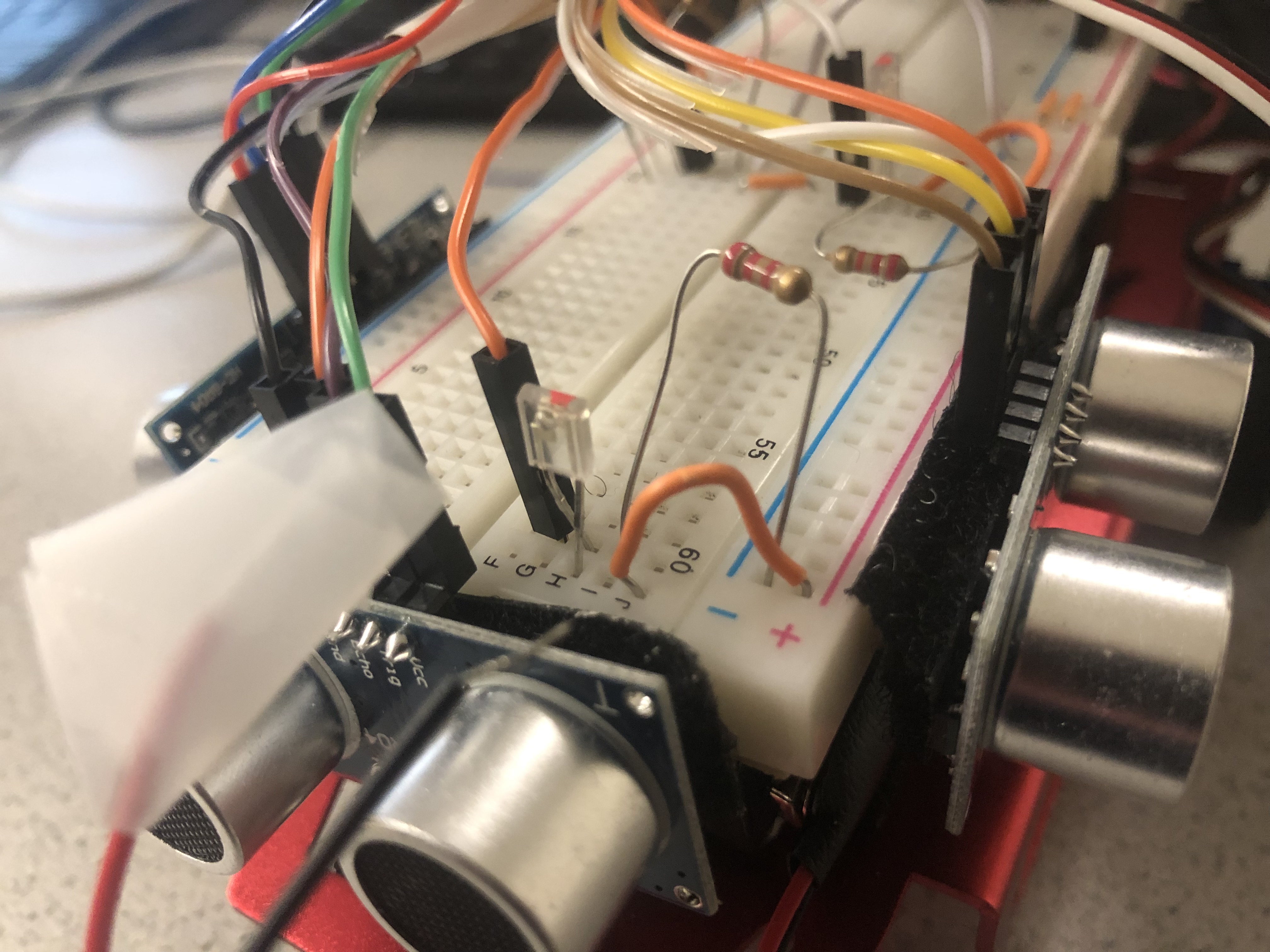
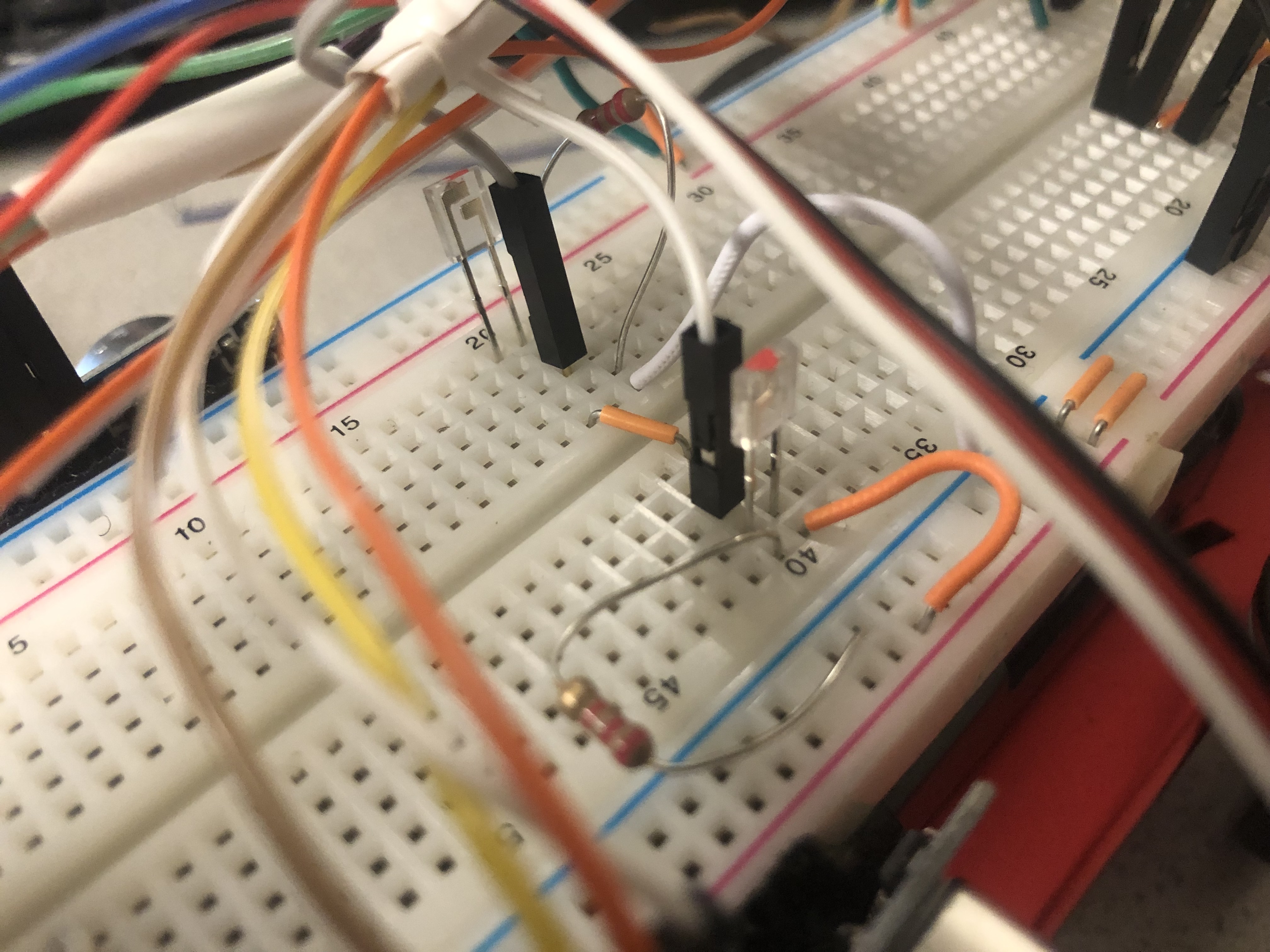
A functionality that we want to implement on the robot is the ability to detect and measure various IR frequencies, then be able to transmit those frequencies to a base station for it to be displayed. In this first part of the lab, the task was to build the light detection and frequency measurement circuit. The circuit was simple, consisting only of a phototransistor and a 2.2k Ohm resistor, which then connected to an analog pin on the Arduino. We built three of these on the front, left, and right so it has full coverage when it will eventually be put into a maze. All the circuits were tied to the same analog pin to save pins necessary for future labs. The circuits built on the robot are shown below.
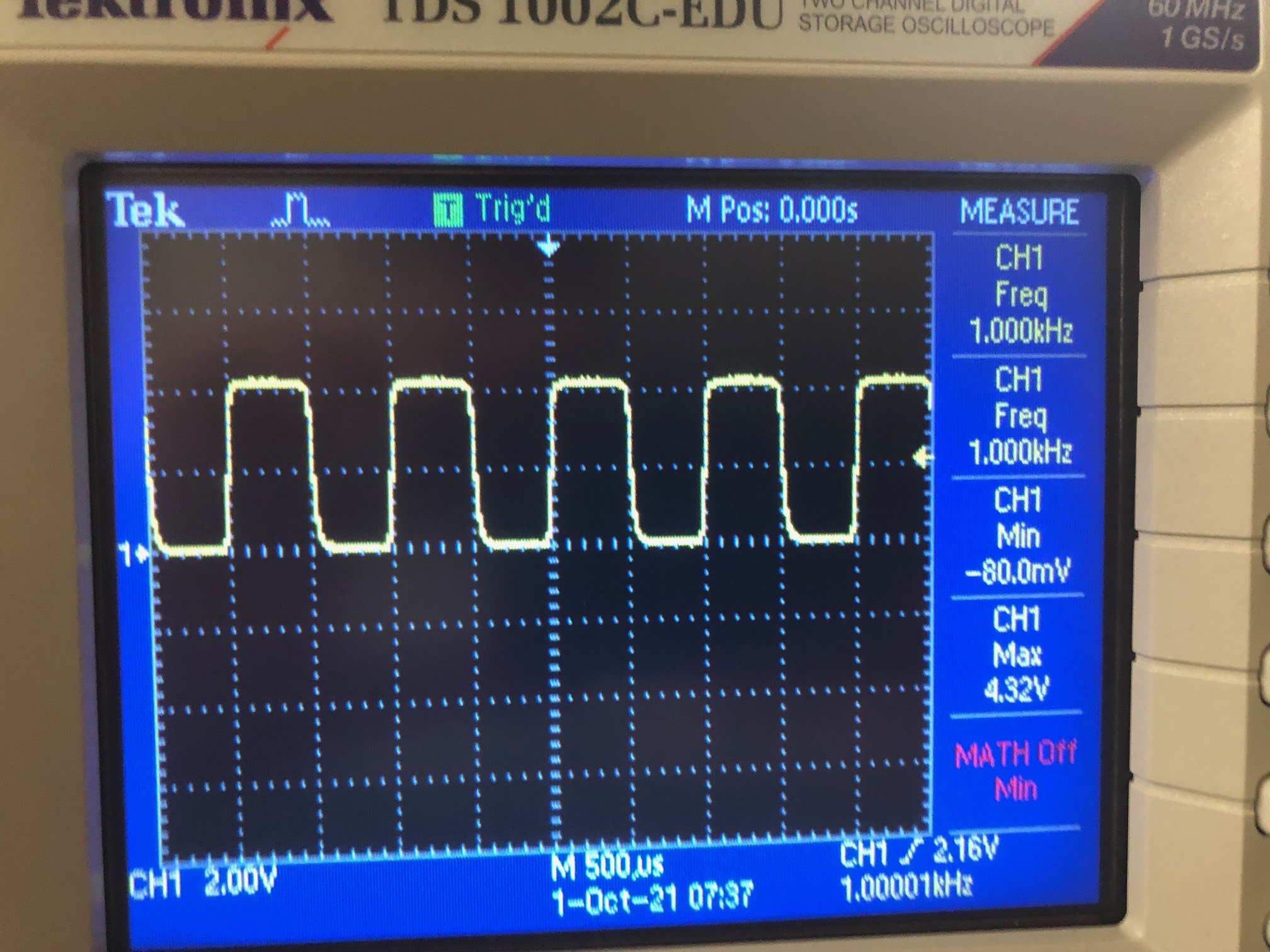
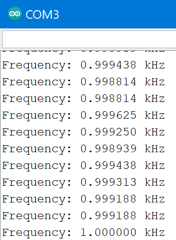
We tested this circuit by placing an IR led emitting a 1kHz signal powered by a signal generator. The circuit was able to accurately measure the signal as shown by the oscilloscope reading below and the Arudino was able to display the exact frequency measurement as well, and shown by serial monitor printout.
4-Digit 7-Segment Display
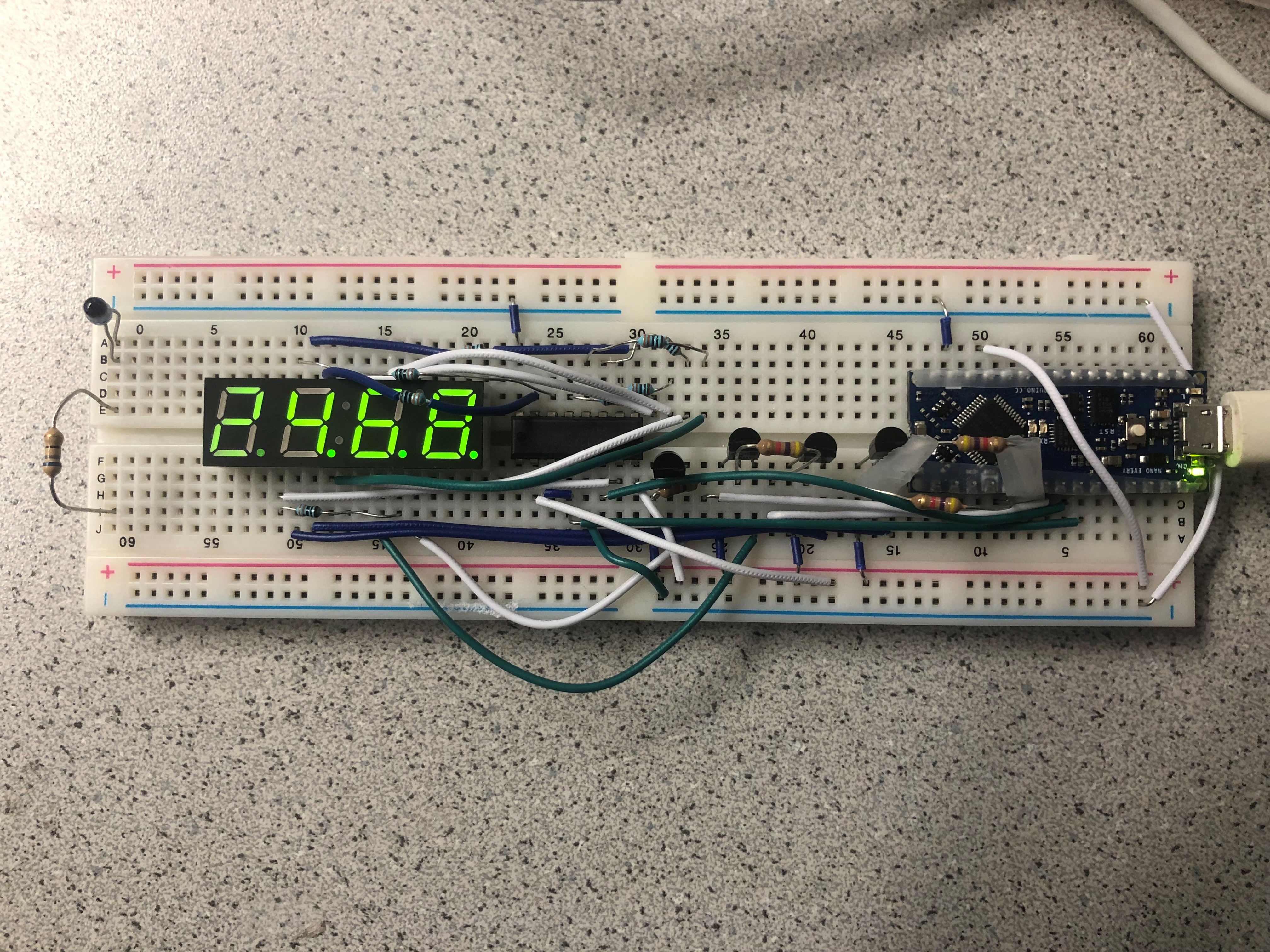
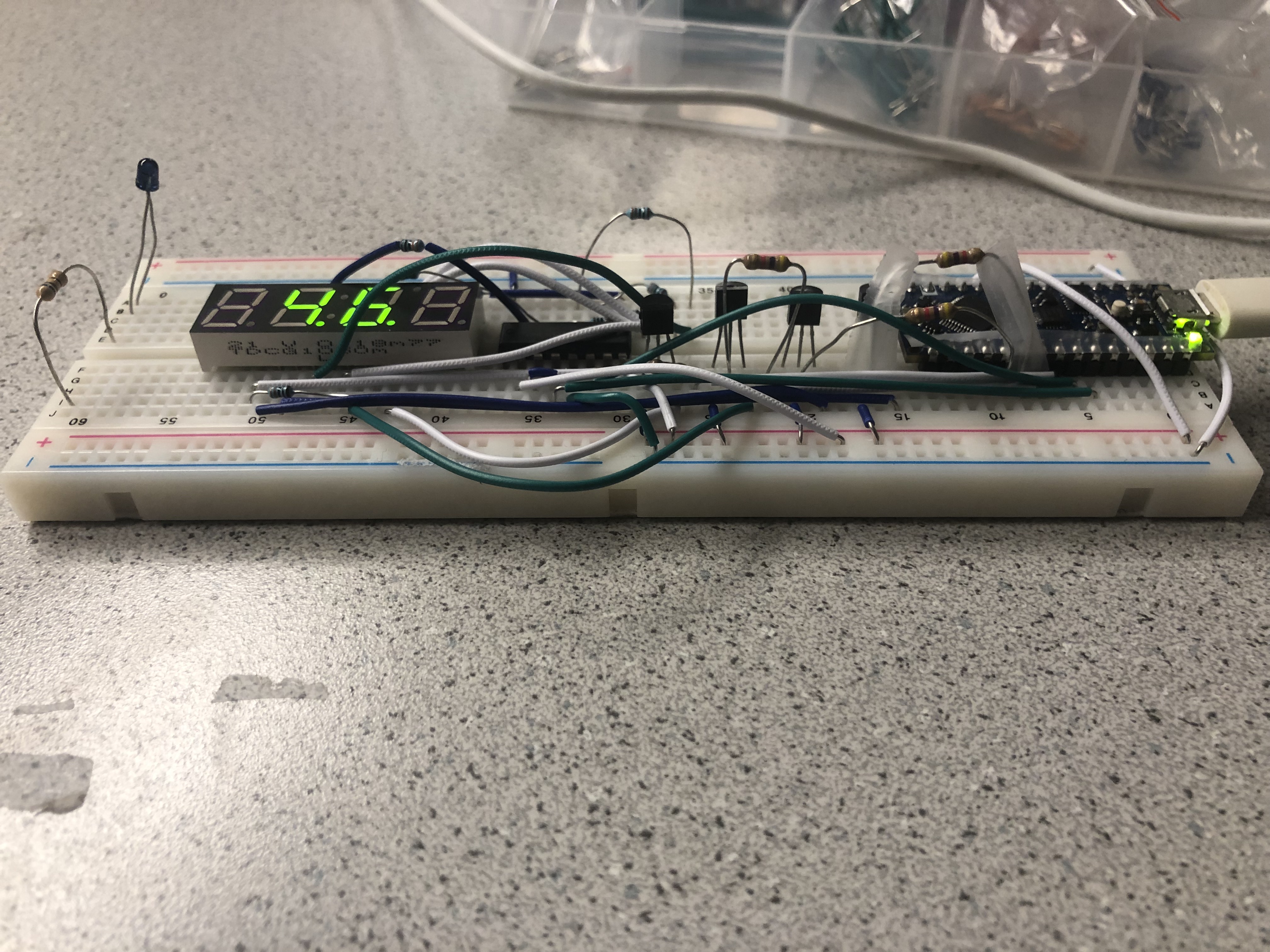
The last part of the lab was focused on the base station where the frequency measured on the robot would be displayed. The circuit we were tasked to build consisted of a shift register, four transistors, eight 330 Ohm resistors, four 4.7k Ohm resistors, and finally, a four-digit seven-segment display, which is displayed below.
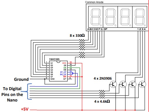
In order for the circuit to actually display something, it needed an additional Arduino Nano Every. With the uploaded code, we tested to make sure that all the individual segments were correct to verify that the circuitry was correct, which is shown by the picture displaying 2468. Additionally, we modified the code to be able to display numbers greater than 9999. To do this, we truncated the number and used to decimal to represent the number in kilohertz as compare to just hertz.
Gallery
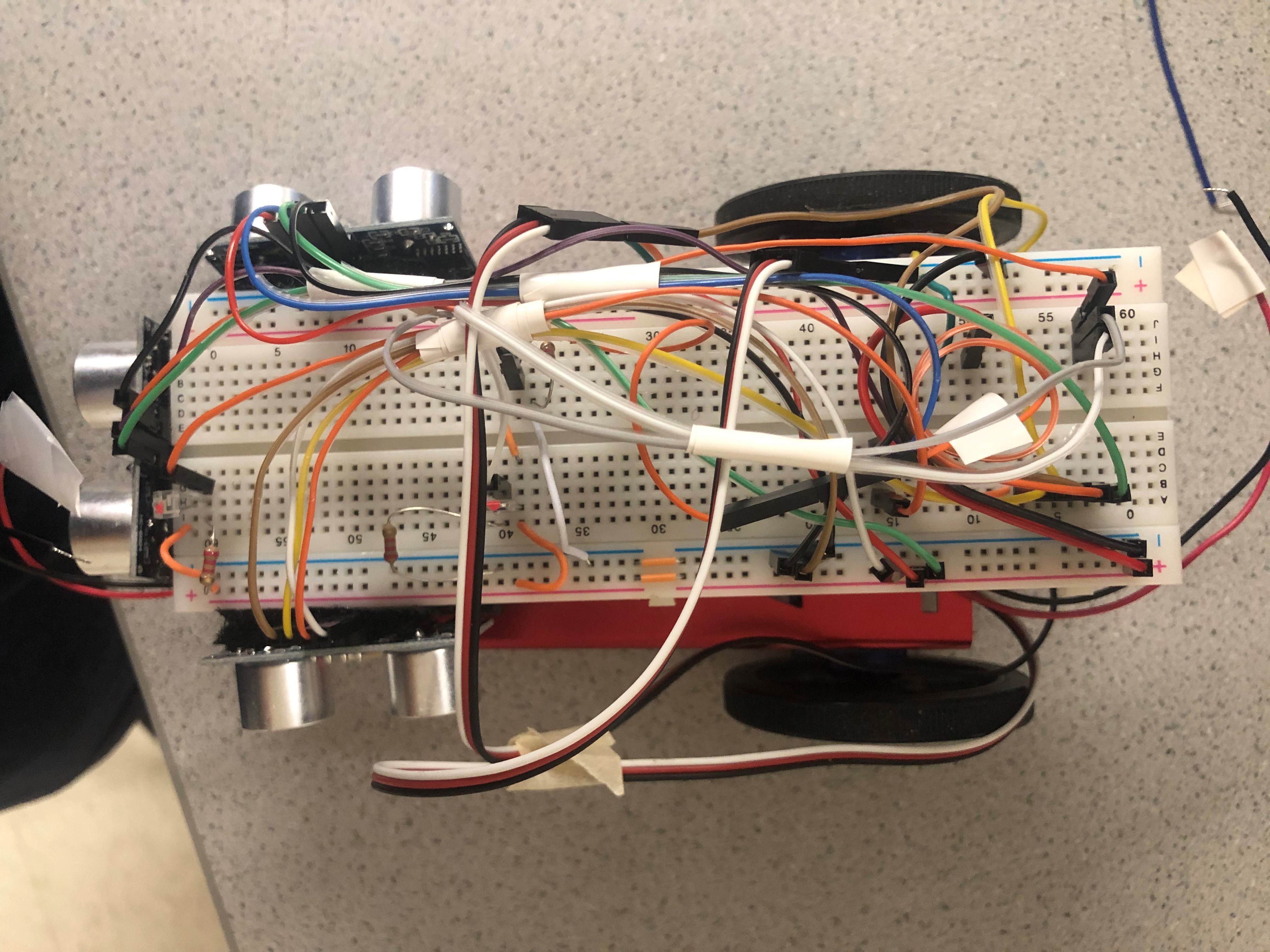
Above is an image of the rewired robot with the new IR detection circuits. We did this so the wires were more organized and less cluttered.