Summary
For lab 1, we first hard-coded a path for the robot to find the best servo speeds for basic motions like moving forward/backwards and turning left/right at different angles. We then added ultrasonic sensors and used them to avoid walls while moving through a short maze.
Part 1: Assembly and Servo Demo
In the first part of the lab, we assembled our robot, added the breadboard, and wired the Arduino and Servos so we could make the robot move. Next, we found the Servo speeds at which the robot moved forward in a straight line at full speed and stopped completely, then created functions to move forward for a variable amount of time, turn right 90 degrees, turn left 270 degrees, and perform other basic movements. Finally, we used these functions to make the robot follow a series of instructions provided in the lab handout and shown in the video below.
Due to the misalignment of one wheel as well as the variability of the Servos, movement functions we had tested at length did not always work as expected; this is clear in our Servo demo video. In the second part of the lab, we aimed to improve these movement functions, in some cases slowing the robot to improve our ability to precisely control its movement.
Part 2: Ultrasonic Sensor Implementation
In the next part of the lab, we added three ultrasonic sensors to the robot, first testing their ability to sense and print out different sets of distances then using the sensors to move through a simple maze. After encountering some problems with the sensors and the provided code, we were able to get the sensors to output accurate readings with some delay. This delay caused initial issues with our robot's navigation through the maze, described later on this page.
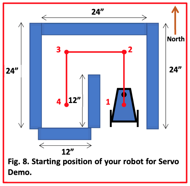
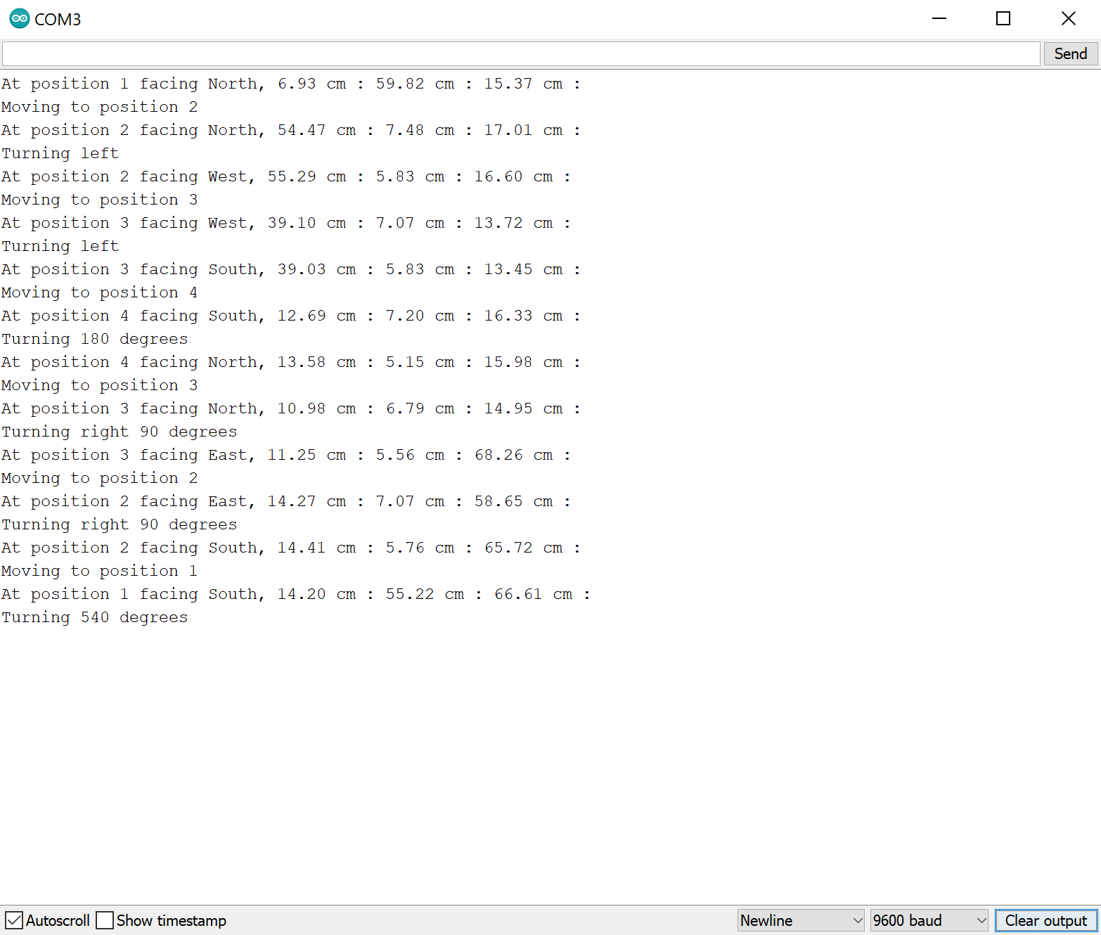
Once we'd completed initial testing of the sensors and our hard-coded movement functions had been refined, we successfuly programmed the robot to follow the above planned path. To do this, we used interrupts to frequently collect data on the time ultrasonic signals took to bounce off an object and return to the robot's sensors. Due to a lack of pins, we used a common trigger pin for all three sensors but three separate receiver pins. Because of the longer time required for calculations, we ommitted those from the interrupts and instead calculated and stored distances for the three sensors only when we planned to use the data. We created a function called "moveUntilWall" where the robot moved forward in short, seemingly-continuous increments until a distance calculation showed the front sensor was close to a wall and the robot needed to stop. Each time the front sensor sensed a wall, we iterated a global variable called "action_state" representing the robot's place in the sequence of instructions to complete the path, then had the robot move according to the next steps associated with its position in the maze.
One of the main challenges we encountered during this part of the lab was the aforementioned sensing delay, causing the robot to retain previous distance values and think it had encountered a wall immediately after turning away from one. We identified that the time the robot spent in front of the object before turning affected whether it would get stuck later, and we learned that delays prevented interrupts from running. We solved this issue by calling the function that updated the stored distance values at key points in the robot's path before invoking delays so the robot did not rely solely on interrupts that could be blocked by delays. A video of one of the successful runs is shown below.
Finally, we changed the code's output to the serial monitor from the constant output we used to debug to a more readable output based on the robot's path, shown below. The values between the colons are the distances from the left, forward, and right sensors (in that order) to the nearest objects, or walls of the maze.