Summary
In lab 2, we worked on the "treasure detection" aspect of our robot by giving it the ability to detect the frequency at which a light was blinking. We also wired and coded a seven-segment display to show numbers up to 10,000 for future use in displaying the detected frequencies.
Part 1: IR Emission and Detection
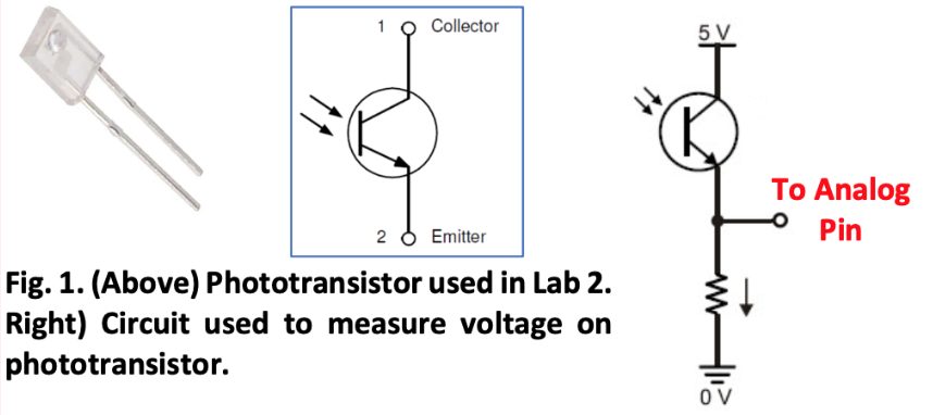
In the first part of the lab, we built IR emission and detection circuits to implement IR light detection on our robot. We started with a simple phototransistor circuit, as shown below. In this configuration, as the light hitting the phototransistor increases in intensity, the voltage at the analog pin on the Nano increases.
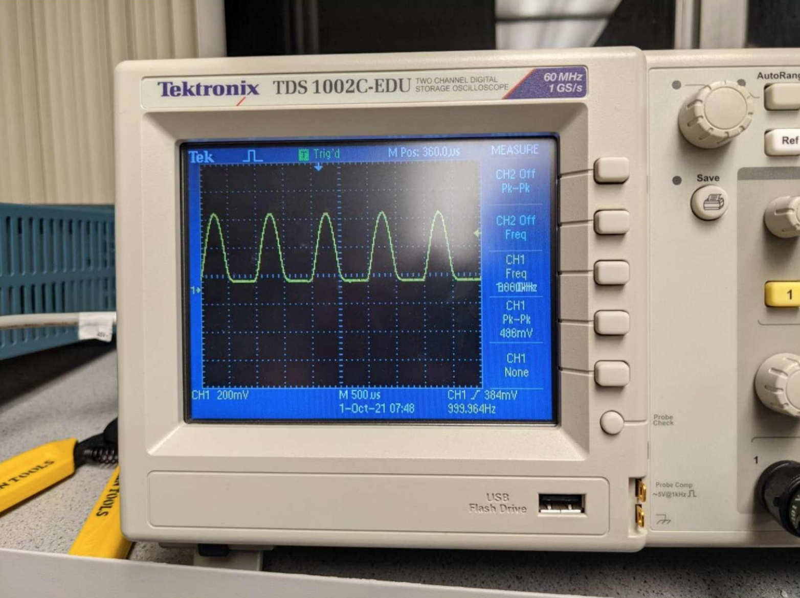
We then tested this circuit using a simple circuit with an IR LED, a signal generator, and an oscilloscope. As the signal generator made the LED blink at a frequency of 1 kHz, we observed the voltage output of the detection circuit and made sure the reading on the oscilloscope also oscillated at a frequency of 1 kHz. We also used the amplitude of the signal on the oscilloscope to determine whether we needed to adjust our reference voltage for light detection.
Once we observed the right signal on the oscilloscope, we connected the output of the detection circuit to an analog pin on the Nano. Using provided code and the analog comparator on the Nano, the robot uses regular interrupts to detect the frequency of the sensed light. We initially found that the phototransistor had difficulties detecting the frequency of the IR LED unless it was very close to the transistor, so we reduced the resistor value on the emission circuit to increase the intensity of light, which made it detect at an acceptable distance away from the robot.
Finally, we built two additional detection circuits on the robot so our robot would not have to physically turn to detect light on three sides. We connected the output of all three circuits to the same analog pin and plan to use Fourier transforms to distinguish between the three signals and select the most prominent frequency to display.
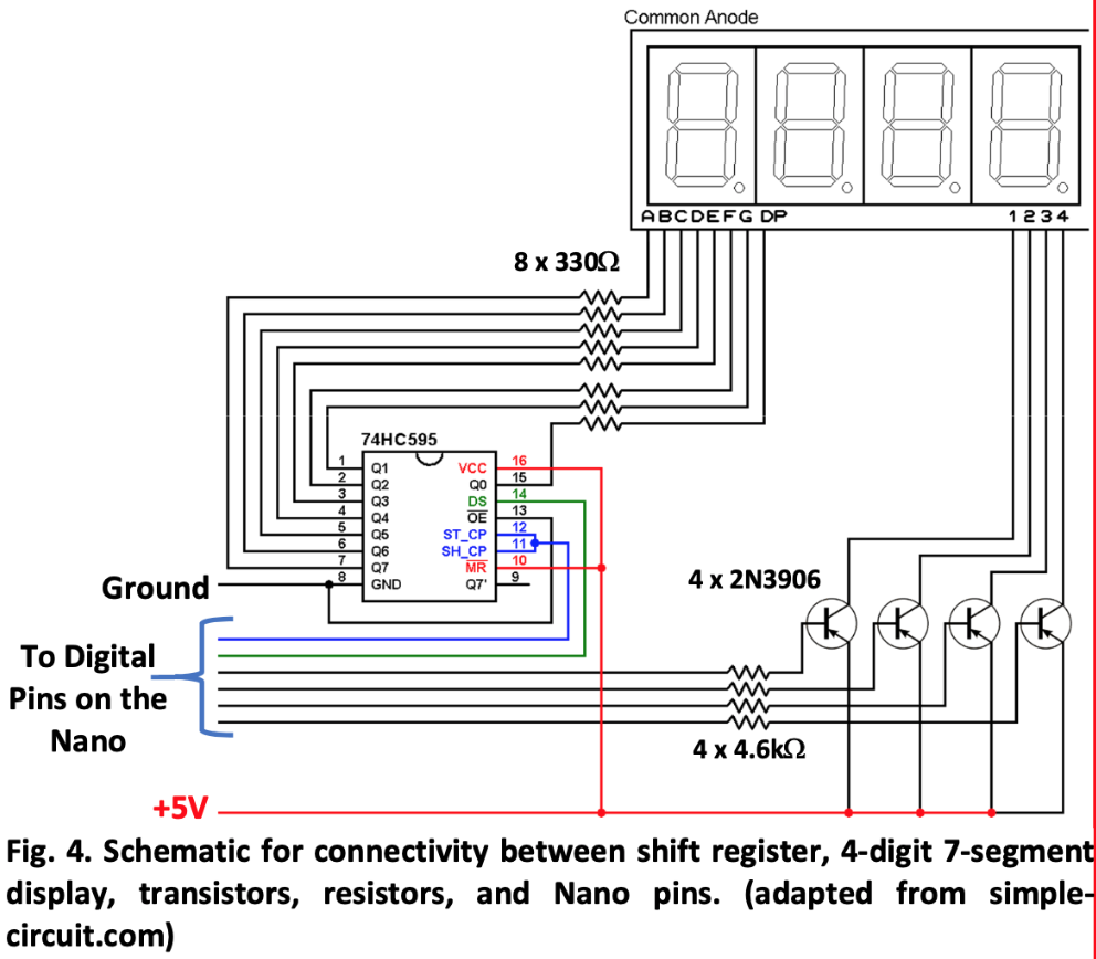
Part 2: Seven-Segment Display
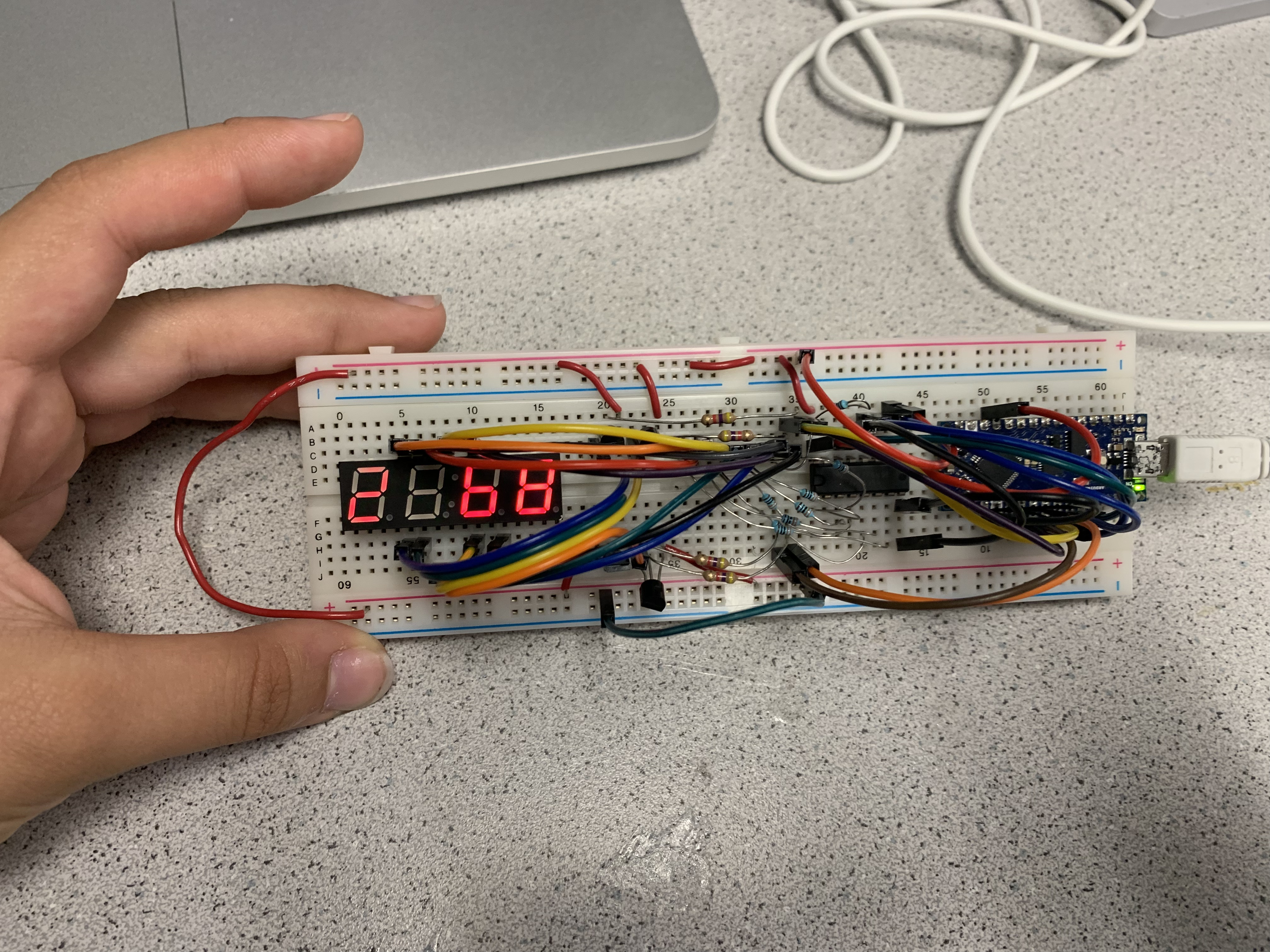
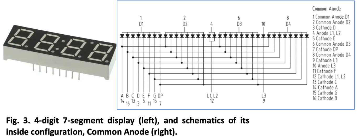
In the next part of the lab, we wired a seven-segment display on the "base station" breadboard, then coded the Nano on the breadboard to display numbers and make use of the decimal place on the display to display frequencies above 9999 Hz. We used the display and schematic shown below to wire the seven-segment display, and we used a shift register to display the four digits on the display using fewer pins on the Nano to leave the other pins free for later use.
This meant only one digit would technically receive current at a time, but the LEDs would stay illuminated for long enough afterwards (and the digits were supplied current at such a high frequency) that this could not be perceived by the human eye. However, a cool photo that captured this phenomenon is included at the bottom of the page!
Once we were able to display "2468" on the board, we then added a few lines of code that would change how numbers were displayed if they went over 9999, using the decimal point to represent them as multiples of 1000.
We had very few issues during this part of the lab; at first, we misread the schematic and caused our display to illuminate the wrong segments, but that issue was quickly resolved.