Lab 6
Objectives:
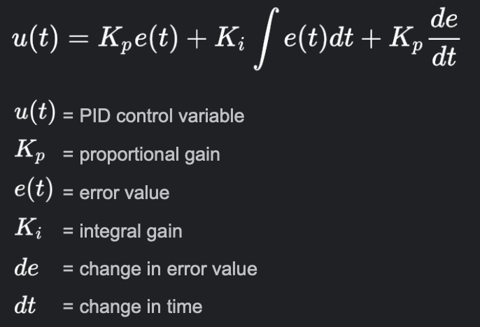
The purpose of this lab is to get experience with PID control. For reference a PID controller is a control feedback loop algorithm that allows you to achieve and regulate a target state using continuosly modulated control. The PID controller consists of three terms that aid in controlling the system: Proportional, Integral, and Derivative. This controller leverages an error value dictated by the difference between the measured state and the goal state. The input for system regulation is informed by the following formula:
Materials
- 1 x R/C stunt car
- 1 x SparkFun RedBoard Artemis Nano
- 1 x USB cable
- 2 x Li-Po 3.7V 650mAh (or more) battery
- 2 x Dual motor driver
- 2 x 4m ToF sensor
- 1 x 9DOF IMU sensor
- 1 x Qwiic connector
Prelab / BLE
Debugging System / Diagram
This lab requires that we execute To collect data and diagnose unexpected behaviors from my robot during the PID implementation, I created a debugging system to aid with that. To collect that data, we have to execute bluetooth communication between the Artemis board and the computer. The task I chose requires that I only collect data from my Front TOF sensor instead of my side sensor and IMU. Notheless, to make the communication process as fast as possible, I used a store and forward communication technique to transfer the data over bluetooth
High-level Overview of Communication and Execution of PID Task
- From the Laptop, send two commands to the car called init_mission & gather_data
- The car would commence collecting data and execute the PID task.
- After 5 seconds, the laptop sends a end_mission command to initiate data capture and signal end of task.
- Upon receiving the signal, the car halts all movements and sends the collected TOF data in the form of an array back to the laptop
- The laptop retrieves and visualizes the data (TOF readings and timestamp) by traversing the array with a loop
One issue that I faced while executing this debugging script was exceeding the allotted memory on the Artemis board. To mitigate this issue, I pre-allocated a size for the data array, that was sufficient enough to collect all the data I needed in a 5-10 second timespan, but also small enough to not run out of memory.
Lab Task
I will be using performing the Don't Hit the Wall task in this lab using only a P controller. Here a P controller simply implies that I'll be neglecting the integral and derivative terms in the above formula when computing the control input to my system.
For each run I performed, I visualized the data to get a better intuition for the behavior of the car based on the changes in the parameter of the P-controller. There were two main parameters I exploited to the generate my analysis of the P-controller: setpoints and gain value.
PID Analysis: Setpoints
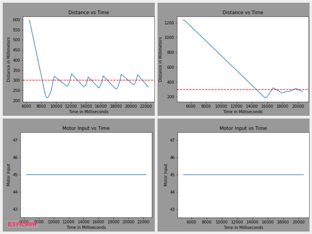
- Attempt 1 with Proportional Gain = 0.04 and Setpoint = 600 millimeters
- Attempt 2 with Proportional Gain = 0.04 and Setpoint = 1200 millimeters
In the figure below, I visualize the behavior of the car shown in the above videos. A few things I observed from this comparison is that with a smaller setpoint the average velocity achieved by the car is greater than when it has a higher setpoint. This trend can be seen by looking at the initial slopes of the two attempts. With the smaller setpoint achieving higher speeds, it is more susceptive to a drastic overshoot. In comparison, the attempt with the higher setpoint does overshoot as well but you can also see that the ringing phenomenon dies out more rapidly and gently than in the other attempt. The attempt with the smaller setpoint has steeper slopes on its overshoot region while the other run has a more gradual approach towards the target distance when it overshoots.
Proportional gain = 0.04 with two different setpoints: 0.6m(Left Plot) and 1.2m (Right Plot)
The Red Dashed Line = Target Distance for the Car: 30cm away from the wall.
PID Analysis: Proportional Gain
The next thing I examined with the P-controller is how the car responds to changes to the gain value despite a stagnant setpoint.
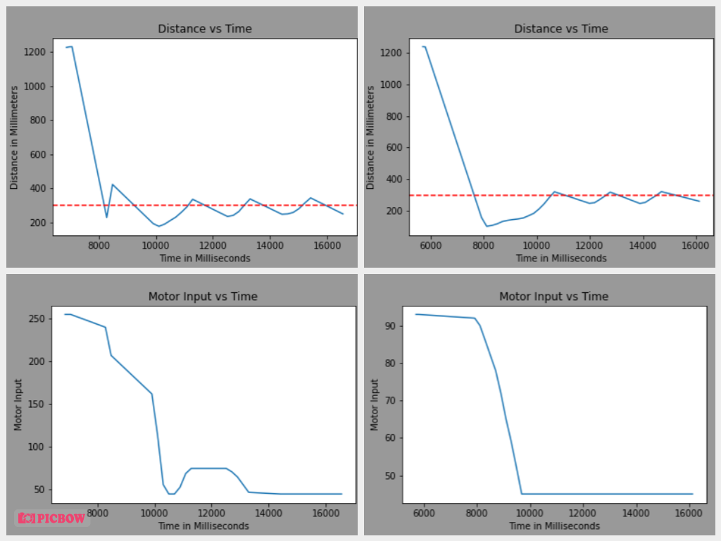
- Attempt 1 with Proportional Gain = 0.1 and Setpoint = 1200 millimeters
- Attempt 2 with Proportional Gain = 0.3 and Setpoint = 1200 millimeters
In the plots below, I graph the car's response in the above video to a change in the proportional gain value. A few things stand out when this parameter is tweaked. Firstly, the initial motor input for the P controller with a gain of 0.3 is much higher than the one with a gain of 0.1. This behavior is expected as the motor input is proportional to the error of the controller. Additionally, the higher gain controller has a steeper initial slope than that of the lower gain. Furthermore, the gain with the higher parameter also exhibits a stronger ringing effect than its counter part. I suppose this could be attributed to the fact that the higher proportional gain value induces a more aggressive acceleration to the car which in turn makes the system more susceptible to overshoot. With the lower gain controller, the car approaches the target more gently and inhibits the car's tendency to overshoot.
Setpoint = 1.2m with two different proportional gains: 0.1 (Right Plot) and 0.3 (Left Plot)
The Red Dashed Line = Target Distance for the Car: 30cm away from the wall.
Key Takeaways
From experimenting with different setpoints and gain values, I learned a few things about using a P controller instead of the full PID controller. First off a P controller is only useful so long as the process we're trying to stabilize is a 1st order unstable process. However, we can only stabilize if we tune our proportional gain to the correct value. In a sense this can be a pro and a con of using a P controller as there is only one possible value for the gain factor but also you don't have to worry about tuning other gain constants of integral and derivative. Additionally, In the context of our robot, using a P controller might not be the most robust option as there are external factors that can invalidate our PID parameters. We can imagine a situation where our batteries are no longer at the same voltage we used to define the original gain parameters or the robot is moving on a different surface with a different kinetic friction coefficient that we originally tuned it with.
In the context of our robot, I also found out that just because you lower the gain factor to supress the overshoot tendency doesn't mean that the ringing phenomenon can be eliminated entirely. There are a few reasons behind this issue. For one, our robot has a deadband zone and thus we can't truly accomodate every value that our PID control generates so we have to clip our system inputs to certain values so it doesn't fall below the actuating motor input. As a result of this limitation we are at the mercy of average velocity associated with our lowest actuating motor input into the system. If our lowest actuating input is not the lowest required input that will get our robot to the target without overshoot, there's not much more we can do to overcome that situation. Furthermore, I observed that there's one big trade off that's made when PID control is between speed and accuracy. I found that amongst my several manipulations of setpoints and gain values, lower proportional gain values which inherently provide slower speeds to the system also inhibits overshoots to the system whereas higher gain values that induce faster speeds to system to get you to your target quickly are likelier to introduce overshoots into the dynamic system. So I guess the question I'd leave with after this lab is: "Are you willing accurately control your system at the expense of swiftness or is speed such a critical component for you that accuracy could be of lower priority ?"