Lab 5
Objectives:
- The purpose of this lab is for you to change from manual to open loop control of the car. At the end of this lab, your car should be able to execute a pre-programmed series of moves, using the Artemis board and two dual motor drivers.
Materials
- 1xRC/Stunt Car
- Sparkfun Redboard Artemis Nano
- USB Cable
- 2x Li-Ion 3.7 850mAh battery
- 2x Motor Driver
Prelab
Displayed below is a schematic of the dual motor wiring featuring the pins I use for logic controls.
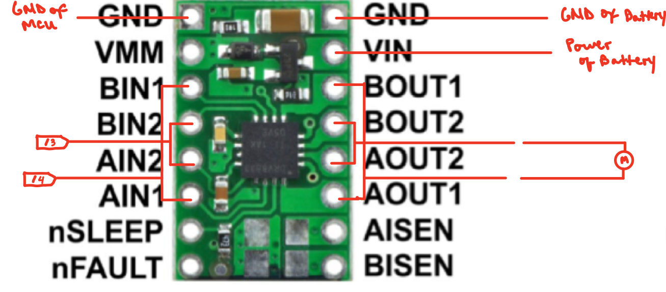
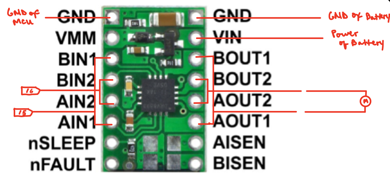
The Artemis and Motor drivers are powered from two different batteries. The Artemis will be powered by a 3.7V 650mAh battery while the motor drivers will be using the 3.7V 850mAh. This battery configuration is due to the fact the motors have a higher currrent demand for operation than the artemis board so they are powered by the battery with a higher capacity.
Routing Comsiderations
With high current operation, electromagnetic interference between signals is a problem that arises. One method I used to mitigate this issue of crosstalk was to twist the wires. By twisting wires that carry an equal and opposite amount of current through them, the interference/noise produced by one wire is effectively canceled by the interference/noise produced by the other thus resulting in a net magnetic field of zero (or close enough). Additionally, when choosing wire lengthsm, I favored using medium length wires over shorter ones, since they provided flexibility for future rewirings. If I ever had to reposition a sensor to somewhere else, I would have enough buffer to make the adjustment.
Tasks
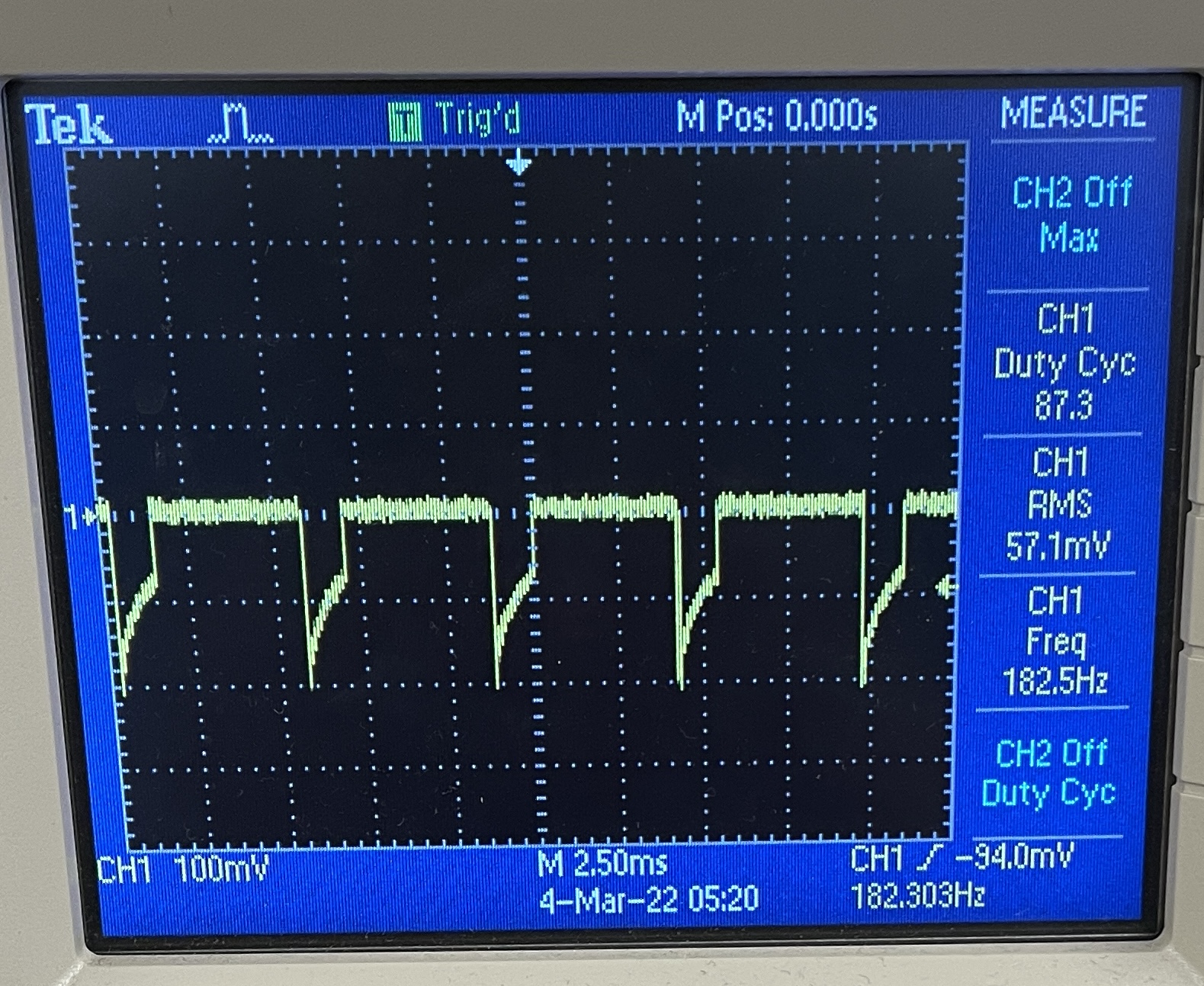
During the lab we were asked to solder connections from the Artemis and motors to the motor drivers as indicated in the above diagram. To validate that the solder connections to the motor drivers were successful and correct, I first supplied 3.7V to the motor drivers using the lab bench power supply, then, via the Artemis, I applied a PWM signal to one of input pins on the motor drivers and used an oscilloscope to probe the outputs. The figure below shows the results of the oscilloscope probe as well as the porgram I used to send this signal.
After validating for an accurate connection, I soldered one of the motors and 850mAh battery leads to the motor driver and applied a PWM signal from the Artemis. Below is the code snippet of the PWM signal as well as a video of the output from the motors when receiving these signals
Since one motor was operational, the second motor was soldered on and a similar PWM signal was applied to get both wheels spinning. Below you can see a video of the two motors running sumulataneously as well as the code I wrote
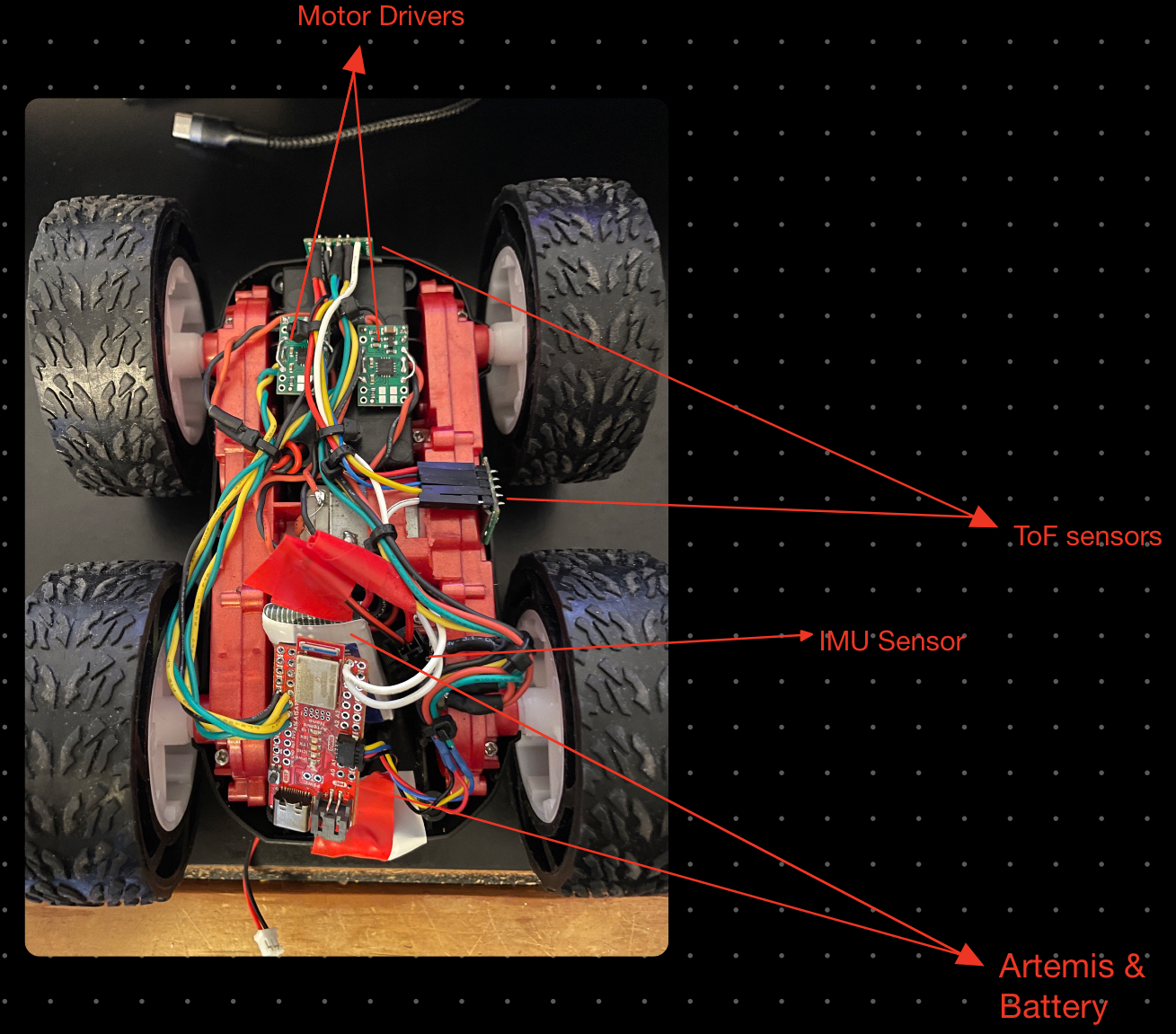
With both motors functional, the sensors could be integrated and secured on to the car. The figure below shows the final assembly of the robot
Open Loop
The program below shows the code I used video to implement open loop control of the robot. Featured below also is a video of the robot executing the code.
Acknowledgement
I would like to thank Prof. Kirsten for helping me resolder the Artemis Board after struggling on it for so long