Ryan's ECE 3400 Wiki
Lab 1
In this first lab, we assembled our robot's frame, built the circuit, and programmed the robot in C++ using the Arduino IDE. These tasks will be described in more detail below.
Materials Used
- Robot frame
- Continuous rotation servos (2)
- Caster wheel
- Screws, nuts, washers
- Arduino Nano Every
- Ultrasonic sensors (3)
- Breadboard and wires
- Velcro and tape
- 5V and 9V batteries
Building the Robot Frame & Circuit
We first built the robot frame by attaching a castor wheel and two continuous rotation servos to a metal body. We then attached a 5V battery to the robot to power the servos, as well as a 9V battery to power the Arduino Nano when we want to operate the robot without it being tethered by a USB cable. Next, we attached our breadboard ontop of these batteries and inserted our Arduino Nano into this breadboard. We uploaded blinking code to this Arduino to make sure it worked. We also used velcro and masking tape to keep everything together, and used regular scotch tape on the Arduino Nano pins to prevent the pins from accidentally shorting.
Servos
After building the frame, we began using the FS90R continuous rotation micro servos.
We first wired the servo power pins into the breadboard's power rails and then connected
the servo signal pins into D5 and D6 of the Arduino Nano. We then calibrated both servos.
To do this we wrote Arduino code that used the Servo.h library and wrote 90 to eash of the servos.
Then we adjusted the turn knob on the bottom of the servo until it stopped rotating.
After we made sure they were calibrated, we worked on the servo code (also using the Servo.h library)
to complete the second lab check off. This involved starting facing north, waiting 5 seconds,
moving 20cm and stopping, waiting 1 second and turning right 90 degrees, waiting 1 second and turning left
270 degrees, waiting 1 second and going south for 20 cm, and finally turning right by 180 degrees and stopping.
We were successfully able to do this and were checked off.
Ultrasonic Sensors
After getting the servos working, we moved onto the ultrasonic sensors. We first wired the sensor pins to the breadboards power rail. Then we wired all the sensors' Trigger pins into pin D3 of the Arduino Nano and each of the sensors' Echo pins into D4, D7, and D8 of the Arduino Nano. Next, we ran the provided ultrasonic sensor code from Canvas to test our sensors. This code uses interrupts to read all three ultrasonic sensors. We tested the sensors by printing the readings of the sensors at the various distances requried for the third lab check off. We were successfully able to do this and were checked off.
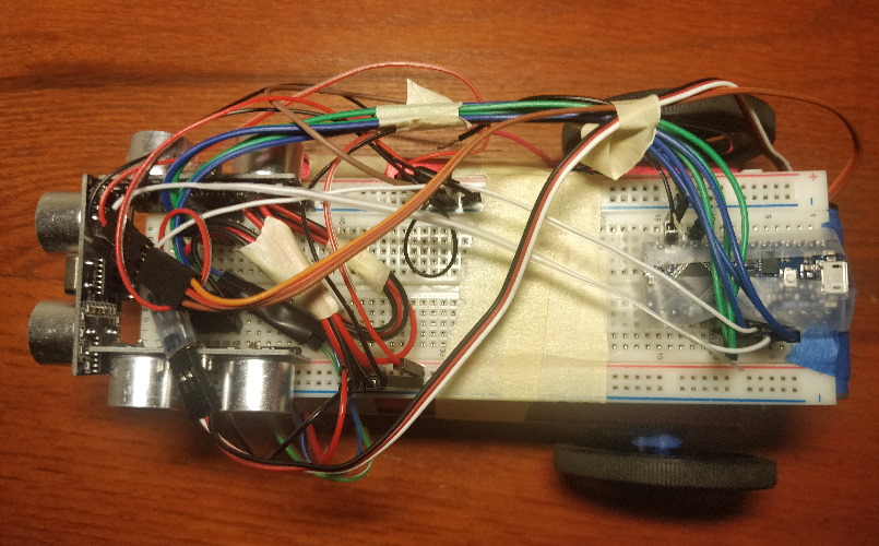
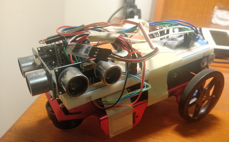
Assembled Robot


Navigation & Video
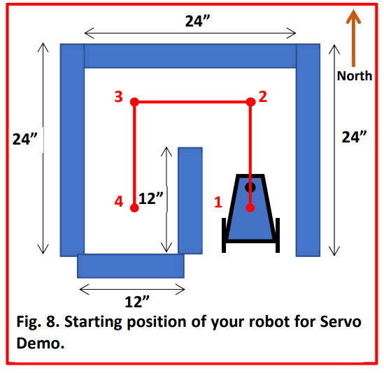
Finally, we combined the servos and ultrasonic sensors to navigate the maze pictured below while printing ultrasonic readings and status messages to the Serial console. It had to reach position 4 in the maze then return back to position 1 and finish with a 540 degree turn. (photo credit: ECE 3400 Lab 1 Handout)

Our approach was to use the front ultrasonic sensor to detect when the robot approached a wall and then perform an action (like turn
for a set amount of time) after detecting the wall. After talking to course staff, this seemed to be the most common approach
to this lab exercise.
We did run into some difficulties with this, however, and performed a very high number of tests until we got one that worked.
The biggest issue was that the servos were extremely hard to use accurately. Oftentimes the servos will turn slightly
more or slightly less each run, which made adjustments to the code hard. These slight imperfections would also eventually
snowball into a failed run.
A possible simple solution to this could be to
add encoders to the list of materials that would give the servos accurate feedback so they can turn more precisely.
Another solution could be to use the side ultrasonic sensors to actively stabilize the robot. However, our team chose
not to do that because the lab handout explicitly banned wobbling, which this type of stabilization is prone to doing.
We also noticed that the servos became more unpredictable and less consistent as the 5V battery pack drained, and we ended up
adding very strange offsets to each of the servos as the battery pack neared depletion. So replacing the batteries with new
ones could have also been a solution.
After many failed runs, we finally produced a succssful run shown below:
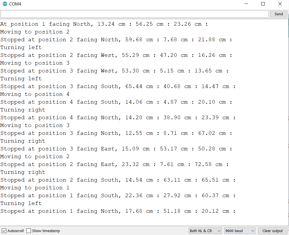
Serial output is shown below:
