Ryan's ECE 3400 Wiki
Lab 4
In this lab, the main additions to our robot were adding an nRF24L01+ Wireless Transceiver so we can communicate with our
base station, and adding a manual override button.
After these relatively trivial tasks were completed, we had to get our robot to complete the final project of this course. This final project
involves navigating a 6 foot by 6 foot maze to find infrared treasures, and then measuring and transmitting the frequencies of the infrared
treasures wirelessly to a separate base station to be displayed on a 7-segment display. All these tasks are triggered by an audio melody
that contains a 950 Hz tone that we had to program our robot to listen to using a Fast Fourier Transform (FFT).
Additions to the Robot
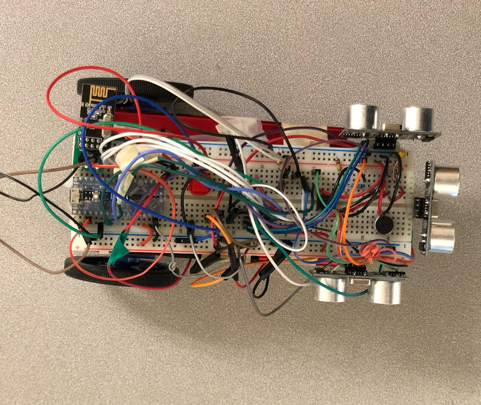
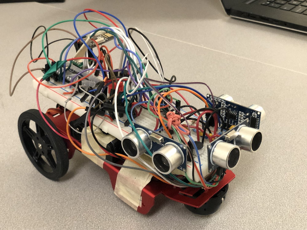
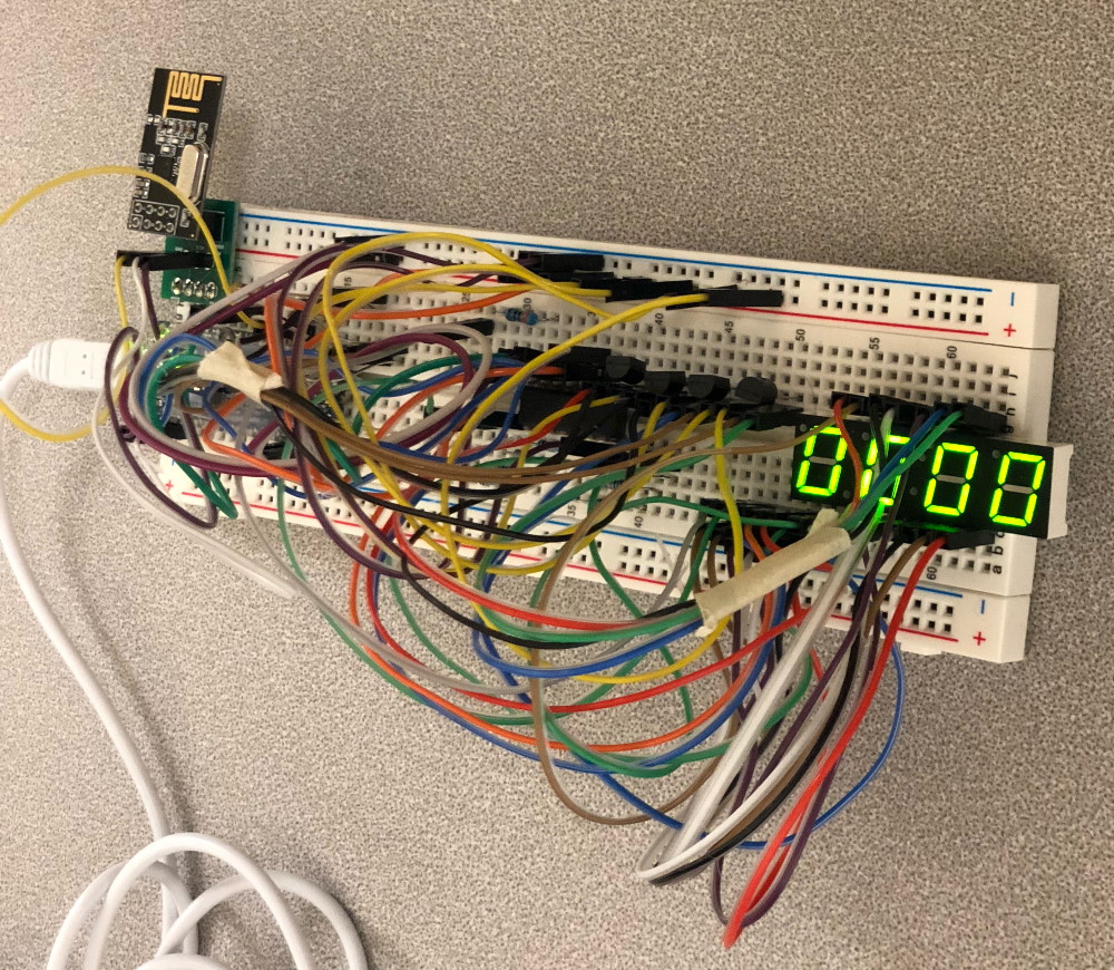
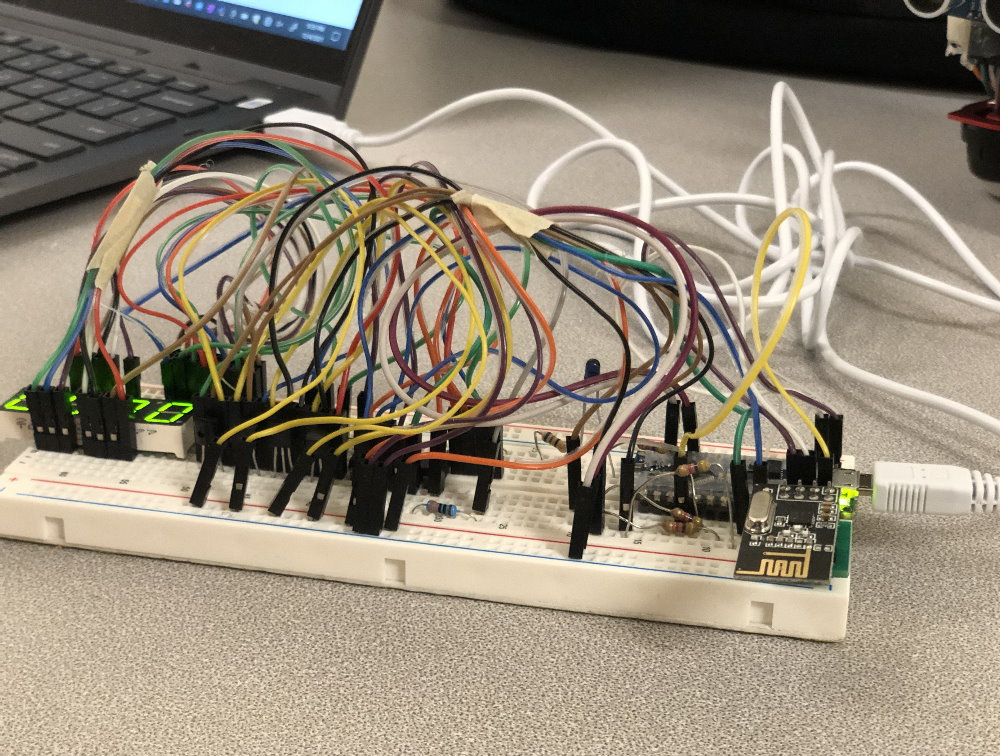
We added two additional components to our robot in this lab. The first was adding an nRF24L01+ Wireless Transceiver to both our robot and our base station so they can communicate with each other. Because the pin configuration on the nRF24L01+ made it hard to put it on a breadboard, we soldered it onto a PCB breakout board, which made it significantly easier to attach to our robot and base station. We were provided transmit and recieve code for the transcievers, which we modified to have the correct pipes so that the robot and base station transcievers can communicate with each other without picking up the signals of other teams. Our next addition was adding a manual override pushbutton to our robot so that it still can start in the event that it does not pick up the 950 Hz starting tone in the melody.
The Final Project
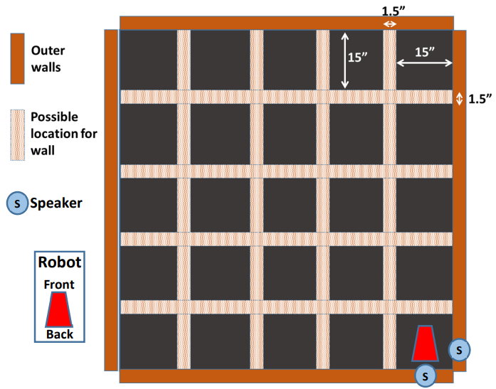
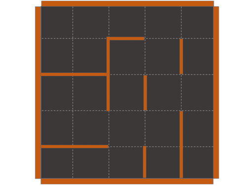
The final project involves navigating a 6 foot by 6 foot unknown maze to find infrared treasures, and then measuring and transmitting the frequencies of the infrared treasures wirelessly to a separate base station to be displayed on a 7-segment display. All these tasks are triggered by an audio melody that contains a 950 Hz tone that we had to program our robot listen to using a Fast Fourier Transform (FFT). This is the culmination of our work in the previous labs and involves integrating everything together as well as implementing an efficient path finding algorithm. Examples of the maze are shown below (Photo credit: ECE 3400 Demo Rules):
• The Initial Navigation Plan
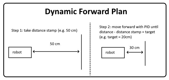
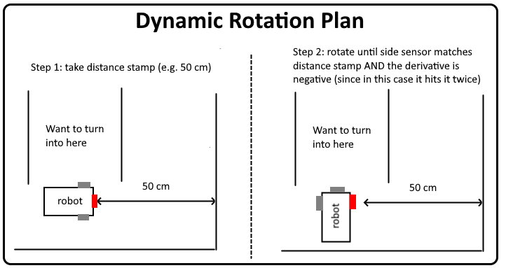
Our initial plan to accomplish the maze navigation was to use a Depth First Search (DFS) algorithm to efficiently traverse the maze. This relies on extremely precise movements and position tracking to work, so we first created a function that could move forward a specific distance by first taking a distance stamp from the front sensor and moving forward until the distance from the initial distance stamp was a specific distance. While this was happening, PID would keep the robot centered. This worked very well, so we then moved on to making precise 90 degree turns by first taking a front distance stamp measurement and rotating the robot until the measurement of one of the side sensors matched the front distance stamp measurement. In some cases, the side sensor would hit the stamp measurement twice, so we handled this by stopping when it hit the front stamp measurement when the derivative is negative. Below are diagrams of our dynamic movement plans:
Unfortunately, 90 degree turns is where we ran into major problems. Specifically, since we used ultrasonic sensors, their
reliance on using reflected sound waves to measure distance led to two major unforeseen issues: reflections and a phenomenon we dubbed the
"Obtuse Angle Problem".
Regarding reflections, we noticed that when the robot is in a corridor surrounded on both sides by walls,
sound waves generated by the ultrasonic sensor on one side of the
robot would end up reflecting and getting wrongly recieved by the sensor on the other side of the robot.
For example, the sound wave from the right sensor would end up getting recieved by the left sensor. This occasionally gives very strange readings. We proved this was the cause when
we noticed that removing one of the surrounding walls completely fixes the issue. Knowing this, we solved this issue by modifying the
ultrasonic sensor code to send out sound waves one at a time and waiting 10ms between them to let the reflections die out (we found that 50ms is recommended in
the datasheet). This gave us accuracy down to about 5mm, but this came at the cost of sampling speed.
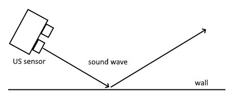
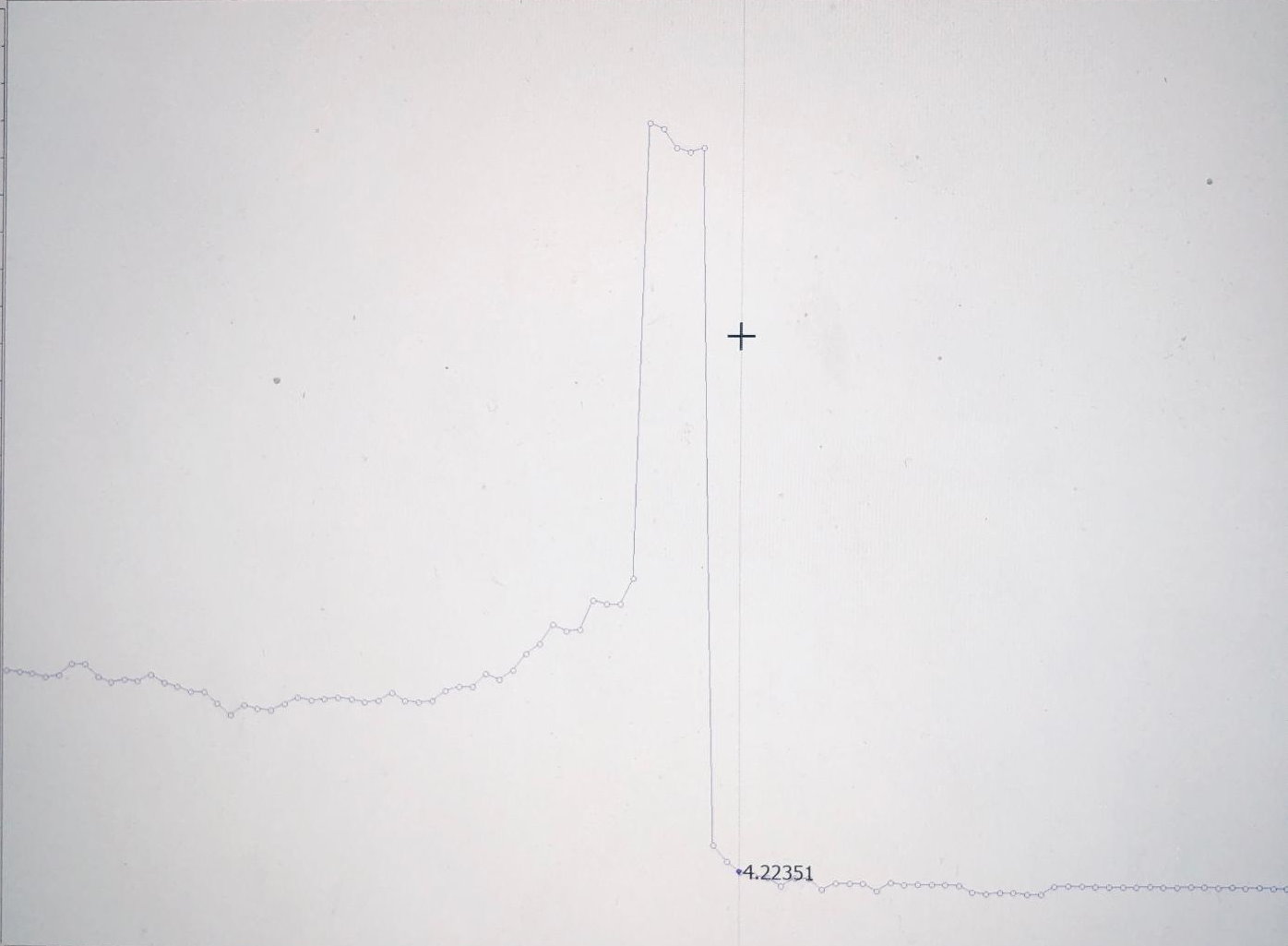
Regarding the "Obtuse Angle Problem", we found that when the ultrasonic sensor is angled past 33 degrees from a wall, the sound wave would end up
getting reflected away from the robot and would either never return or return from a much farther distance. This gave us incredibly high readings
during this point, which we dubbed "The Dark Zone", which made it impossible to detect when to stop turning in our algorithm. Specifically, our algorithm would confuse
a part of "The Dark Zone" with the stopping point (when the side sensor matches the front distance stamp and derivative is negative), and stop about half way.
We unfortunately found this impossible to solve due to the laws of physics.
Below are diagrams of the "Obtuse Angle Problem" and a Serial Monitor plot of our data showing this:
Although we found the process of discovering these issues very intellectually stimulating, we wished that the professor had done his own testing to discover and make known these issues beforehand. • The Final Navigation Plan
After coming to the conclusion that DFS was impossible to solve due to the laws of physics, we made the decision to switch to a more
brute-force method of solving the maze.
After discussing our findings from above with the professor, he agreed to reduce the maze difficulty for the entire class so that a Right Wall Following
Algorithm would work. To accomplish this, we scrapped all our code from above and implemented a very straightforward algorithm: if
the front wall is close (i.e. front sensor measures less than 5 cm) then make a hard 90 degree turn, else if there is nothing on the right
(i.e. right sensor measures greater than 38 cm) then make a curved turn right, and if none of those above two cases are met, go forward with
PID to keep the robot going straight. We found that making a curved turn right was the hardest part, but we eventually tuned it to a point
where the algorithm would smoothly transition from a curved turn to locking onto a wall and moving forward with PID. We also found that our
left sensor was completely not used, which unintentionally solved the reflection problem mentiond in the Initial Method section. This algorithm
ended up working surprisingly well and below is a video of this algorithm in action during our Final Demonstration:
• Integration of Everything
Our next task was to integrate all the different parts of the labs together. We accomplished this by simply merging all the code from
the previous labs. For the most part this was simply copying and pasting code from previous labs (more information about these
in the dedicated Lab 1, Lab 2, and Lab 3 pages) into a main file. We then organized the code into separate functions that we called so the main setup and loop
functions won't be hundreds of lines long, and then tied them together. This was fairly straightforward, but we did have to modify the FFT
code quite a bit so that it would detect a specific tone. To do this, we turned the code into a function called calculateFFT that would return
true if it detected the 950 Hz target tone and or false if it didn't, and continuously polled this function if there were enough samples.
To check if it detected the 950 Hz target tone, we had a for loop that looped through a subset of bins around the bin corresponding to
950 Hz to check if any bin had a value over 50.
However, we did run into major issues with the interrupts during our integration. The first issue we discovered was that the TCA interrupts for the FFT audio ended up taking out our servo control since they both use the
same timer. This was easily fixed by disabling the TCA interrupts after we finished the FFT audio sampling. We then ran into a more subtle bug
again with the FFT interfering with the servos, where sometimes the servos would work perfectly and sometimes the servos would not work at all
at a very random chance. After much testing, we narrowed it down to the FFT again and then further narrowed it down to interrupts since that
would be the only way for this to happen randomly. Specifically, we found that with the way our code was setup, the TCA0_OVF_vect ISR would sometimes trigger
at a critical point that would mess up the timer settings for the servo setup. We resolved this by making that critical section of the code atomic by disabling interrupts
during that point.
Our next issue was again with interrupts. With the way our code used to be set up, while the robot was turning or moving forward, it would
continuously poll the infrared frequency value (if there was one), and send a radio signal to the base station if it had a valid value.
However, sending radio signals required the disabling of interrupts, which ended up locking our servos in the middle of movements. We
resolved this by queueing a radio signal to be sent after a turn was completed.
Once these issues were resolved, we were able to successfully complete the Final Demo with a score of 23 out of a possible 25.
