Ryan's ECE 3400 Wiki
Lab 2
In this lab we assembled and tested our robot's IR light detection circuit that will allow us to detect the treasures in later labs, and we also built the display for our base station that will also be used in later labs to display the frequency of the treasure. These tasks will be described in more detail below.
Materials Used
IR Light Emission & Detection:
- Breadboard and wires
- Resistors
- Phototransistors
- IR LED
- Signal Generator
- Oscilloscope
Base Station Display:
- Breadboard and wires
- Arduino Nano
- PNP transistors
- resistors
- SN74HC595N shift register
- 4-digit 7-segment display
IR Detection Circuit and Testing
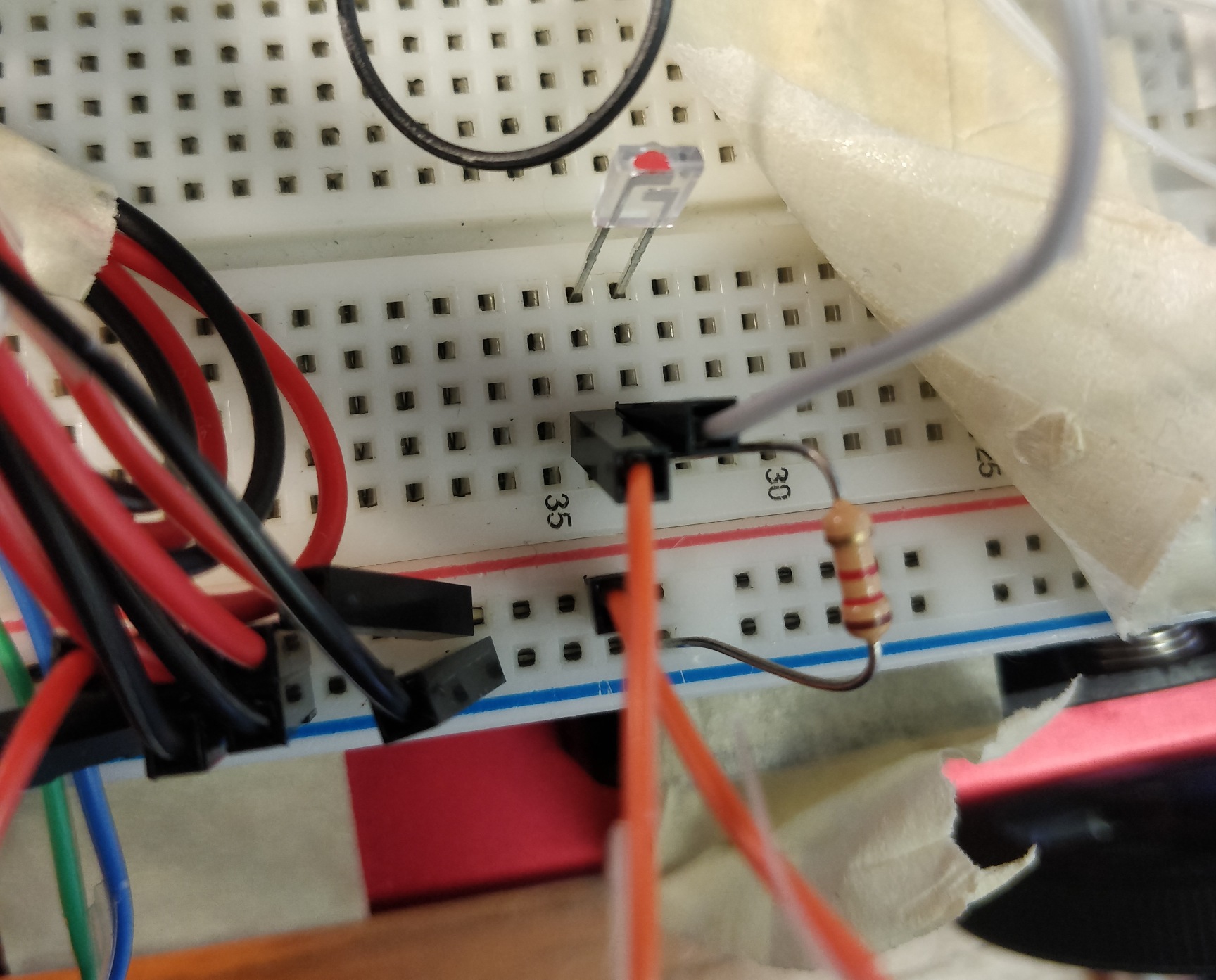
We started by building the photodetection circuit that will allow us to detect the treasures in later labs. This consisted of a phototransistor and resistor. A schematic (photocredit: ECE 3400 Lab 2 Manual) and picture of our circuit is shown below:

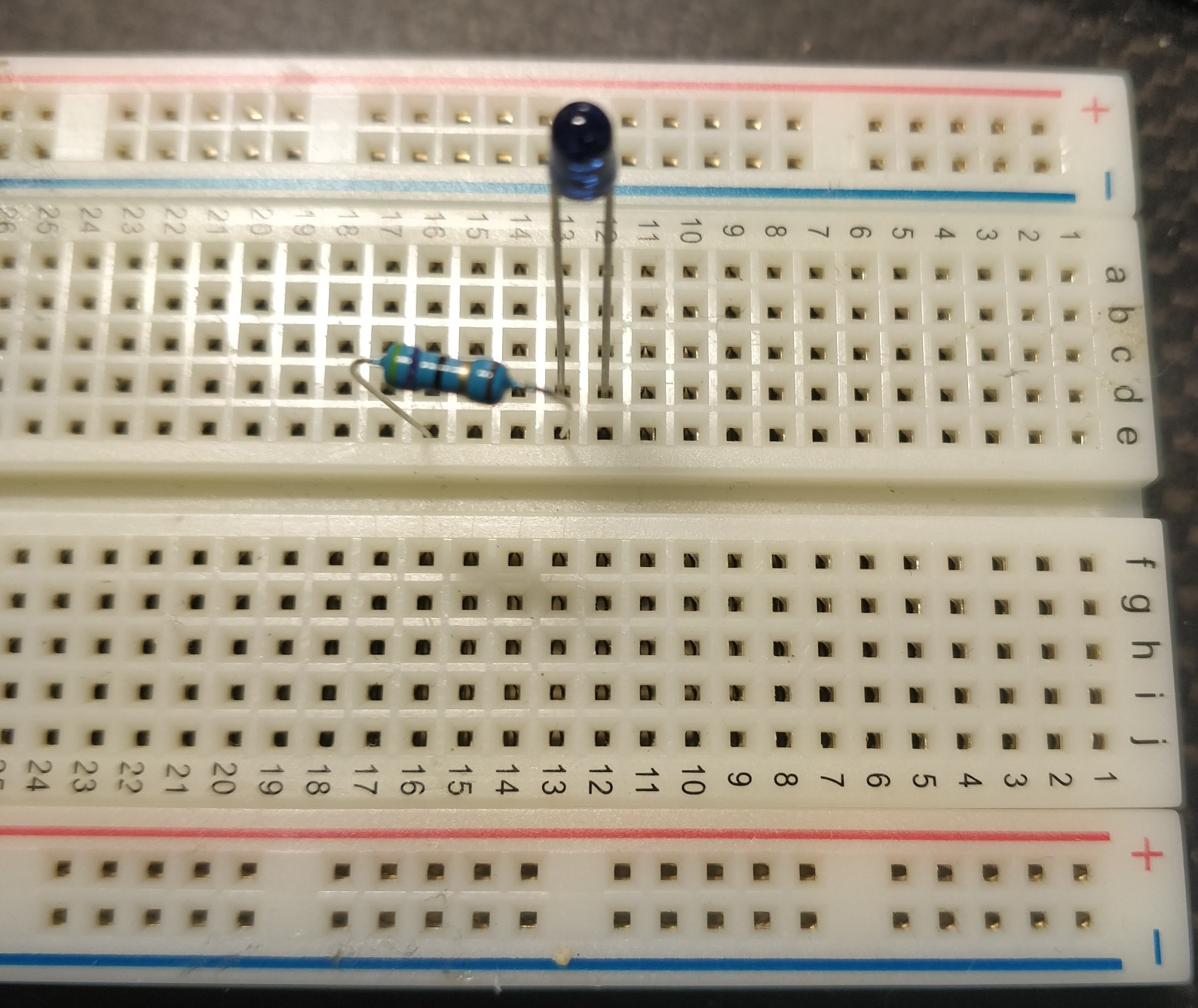
To help test this circuit, we next built an IR LED circuit connected to a signal generator that will blink the LED at a certain frequency specified by the signal generator. This IR LED circuit was fairly simple and consisted of an IR LED in series with a resistor connected to a signal generator. We had to choose a resistor so that 20mA of current will flow through the LED when it is at 1.2V, so we chose resistor of about 60Ω for this. A picture of this circuit is shown below:
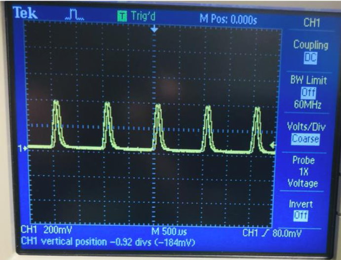
We set the signal generator to output a sinusoidal waveform with a frequency of 1kHz and peak-to-peak voltage of 1.2V. Before we connected the signal generator to the LED circuit, we connected it to an oscilloscope to make sure it was outputting the signal correctly. We confirmed that it was with the oscilloscope measurement reading 1kHz, and got checked off by the TA for that section. After confirming that the signal generator is working correctly, we connected the oscilloscope to the phototransistor circuit and got a good reading of the 1kHz signal. A picture of this is shown below:
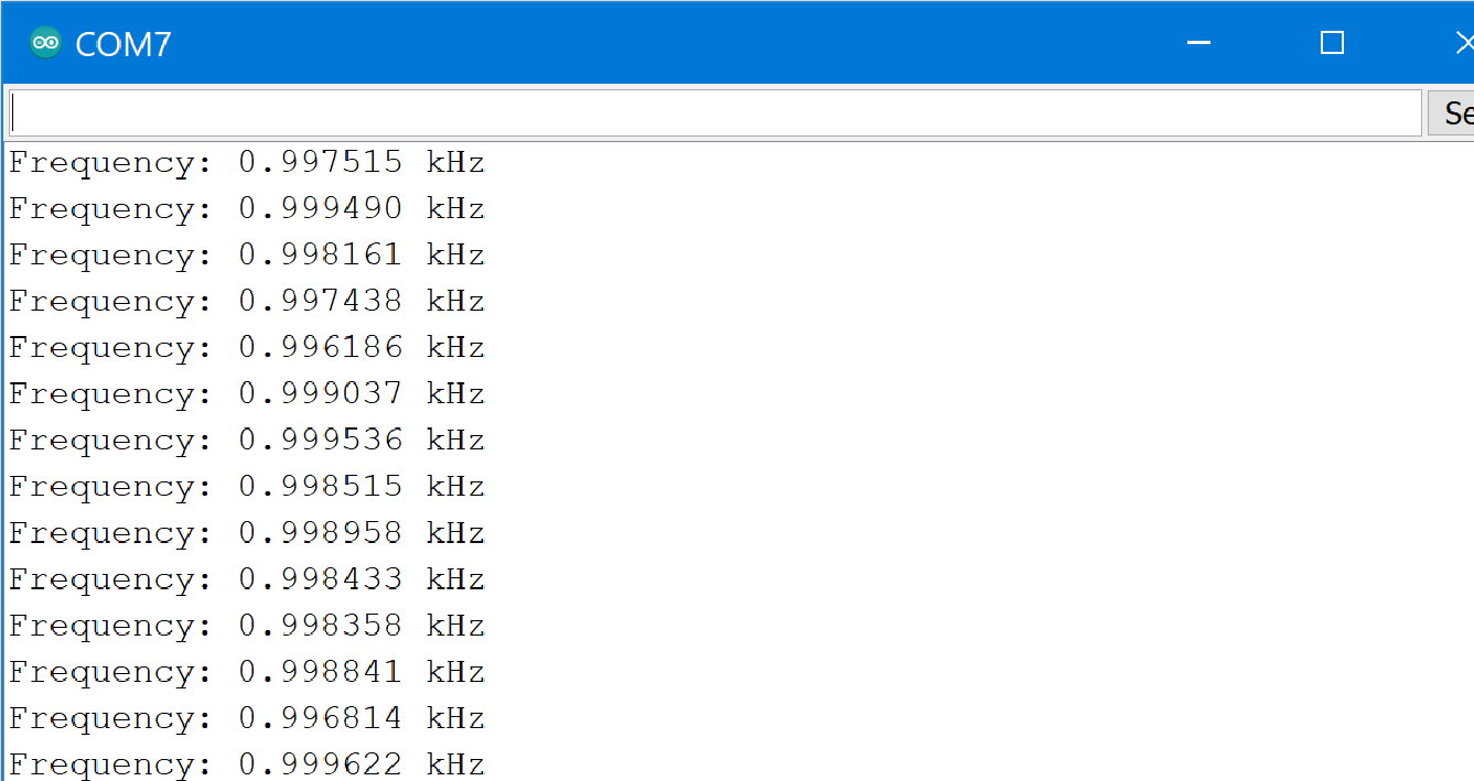
We then used the Arduino Nano to measure the frequency by connecting the output of the phototransistor circuit to analog pin A1 of the Arduino Nano and running the provided "AC_readPhototran_Canvas.ino"code from Canvas. With this setup, the Arduino Nano correctly measured the frequency to be about 1kHz, which is correct. A picture of this is shown below:
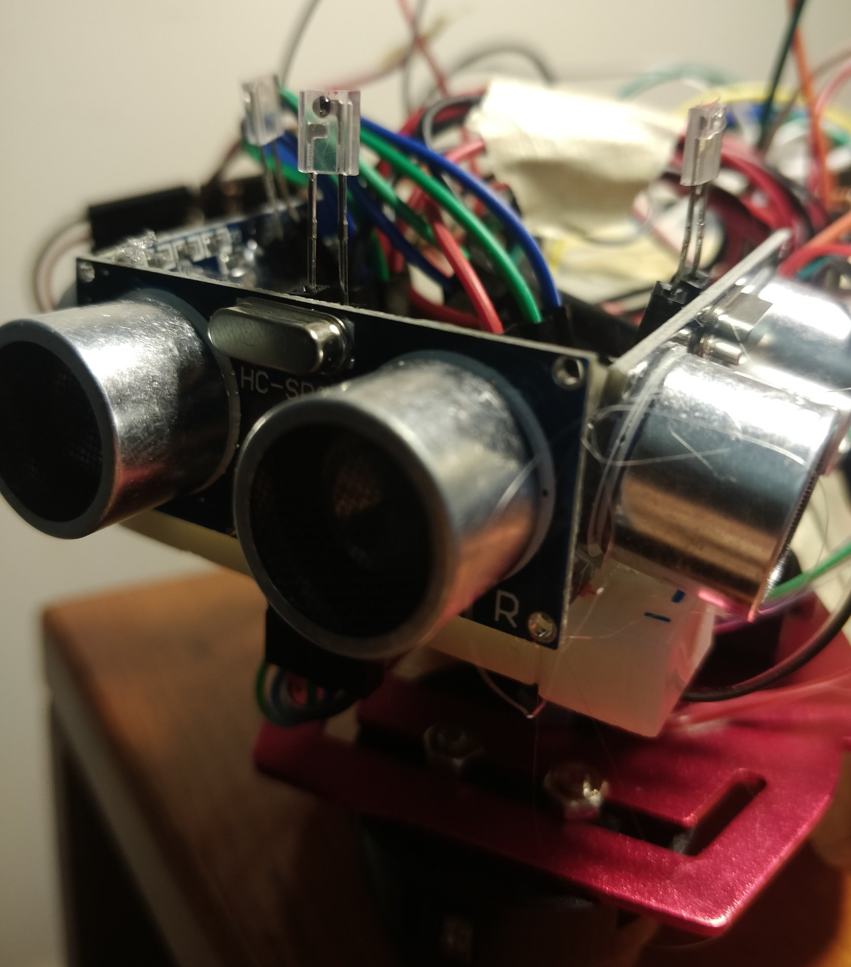
Finally, we added two additional phototransistor circuits for a total of three phototransistor circuits to our robot so it can detect the treasures more easily in later labs. We positioned them in the same way we positioned the ultrasonic sensors by gluing the phototransisors onto the ultrasonic sensors and having wires going out of the transistors connecting into the breadboard. We believed that this would give us the best coverage to detect the treasures. A photo of this is shown below:
The 4-Digit 7-Segment Display
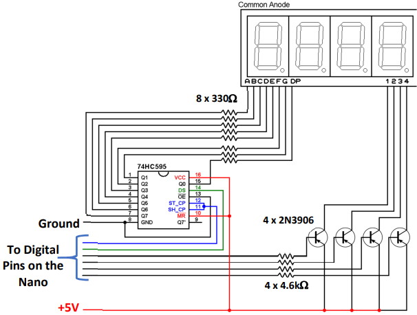
In addition to the IR Detection circuit, we built the display for our base station that will also be used in later labs to display the frequency of the treasure. This consisted of another Arduino Nano, a 4-digit-7-segment display, resistors, breadboard, transistors, and a shift register wired together according to this schematic (photocredit: ECE 3400 Lab 2 Manual):
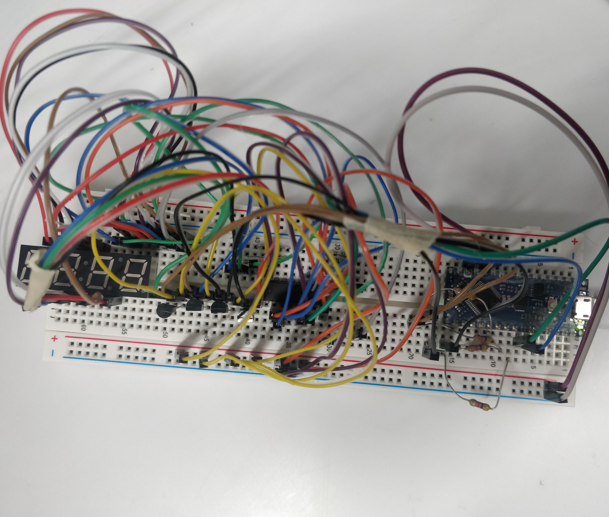
We then wired the display circuit to pins D2-D8 on the Arduino Nano as specified by the Lab 2 Manual. A photo of the completed display circuit is shown below:
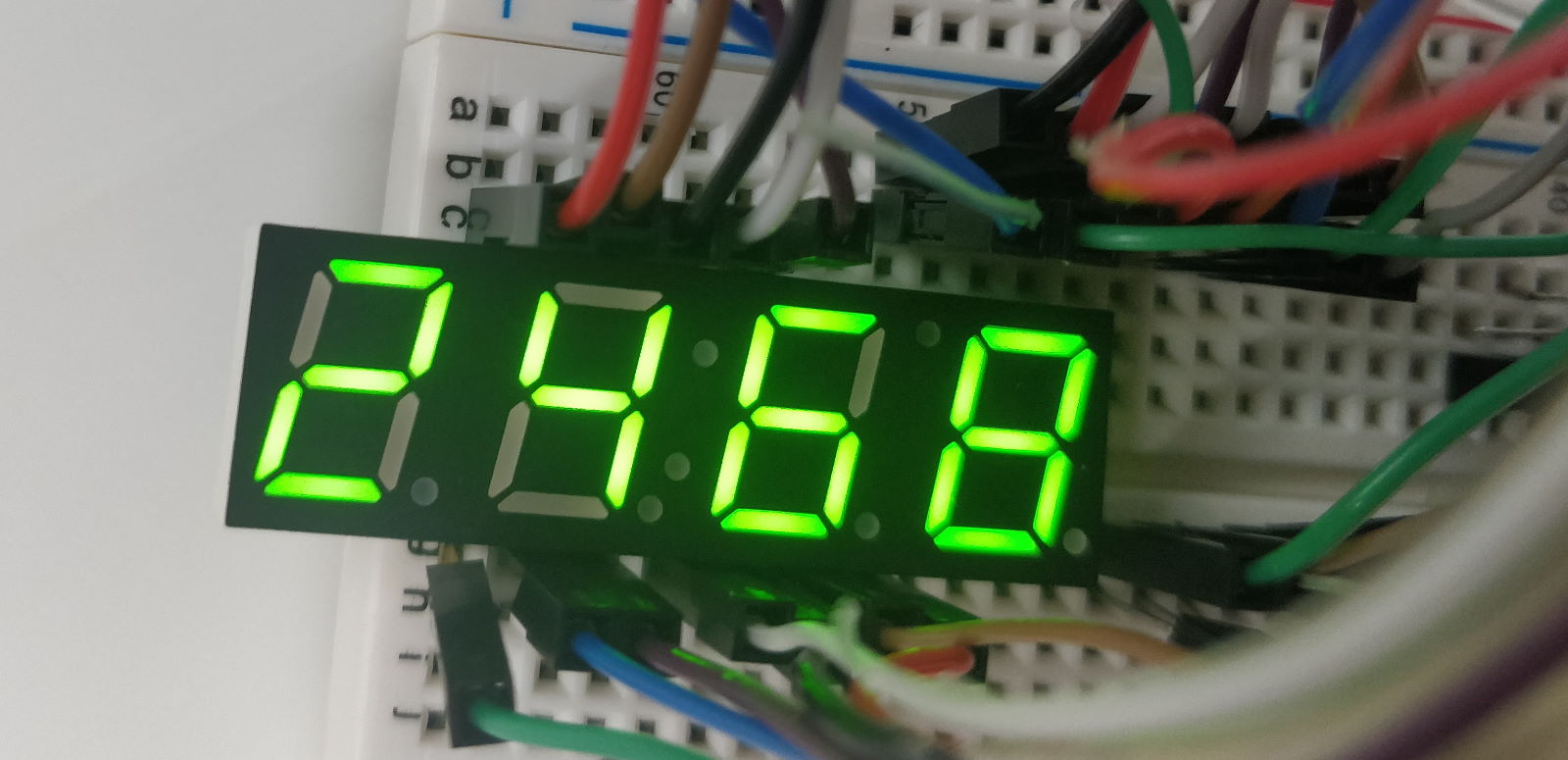
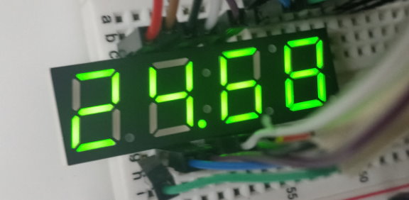
Next we tested the display by running the provided "7Seg_Canvas.ino" code from Canvas and changing the displayed number to "2468". Originally, our circuit did not work because because we accidentally used MOSFET transistors instead of the PNP transistors specified by the lab manual. Once we fixed this mistake, our display showed the correct numbers, and we were able to get checked off by the TA. Finally, we modified the provided code so that it could display numbers greater than 9999 by adding in a decimal point to indicate kilohertz. Photos of the displayed numbers are shown below (left without a decimal by printing 2468 and right with a decimal by printing 24680):