Lab 1
Objective
The objective of this lab was to learn how to program an Arduino, and then write code to read the voltage values from two photoresistor circuits to set up the light sensing capability of my light‐following robot.
Materials
- (1) robot kit
- (1) Arduino Nano Every
- (1) breadboard
- (2) CdS photoresistors
- (2) resistors
- (2) M-M jumper wires
Process
Hardware
Two cadmium sulfide (CdS) photoresistors were used in this lab to serve as the two eyes of the robot. These parts change resistance based on how much light impinges on them; the brighter it is, the lower their resistance. The specific photoresistors that I used have a resistance of 0.5 MOhm when in near complete darkness, while having roughly 20 kOhm resistance when exposed to a lot of light. By using a voltage divider circuit and reading the output with an analog pin on the Arduino for each photoresistor, I could obtain the approximate direction of the brightest light source nearby based on which pin had a higher reading.
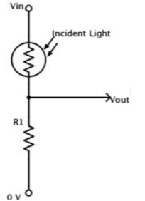
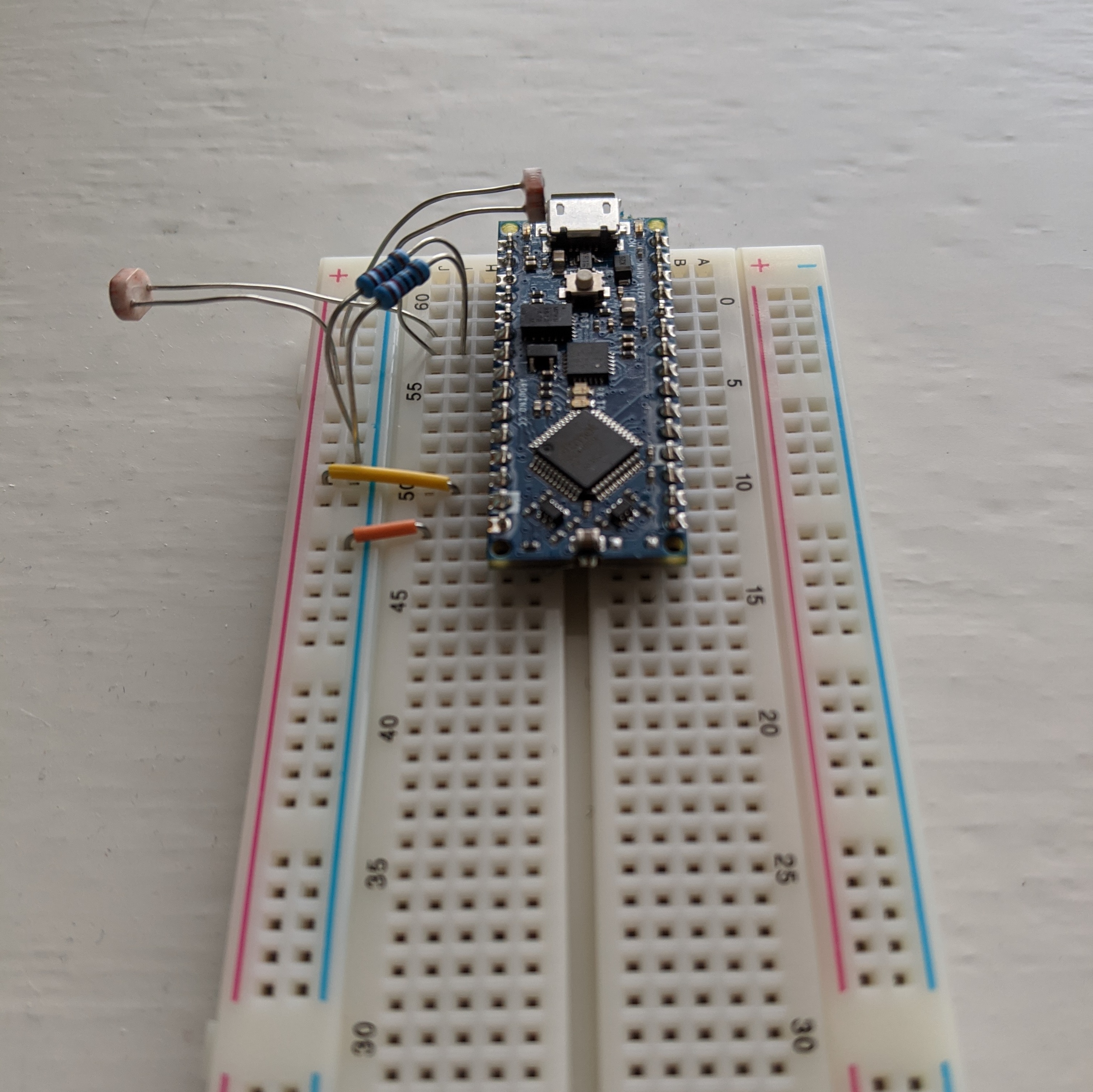
The voltage divider circuit pictured above was used twice, one for each photoresistor. I used the +5 V pin in the Arduino as Vin, a 10 kOhm resistor as R1, and connected Vout to an analog pin on the Arduino. The final result is pictured below.
Software
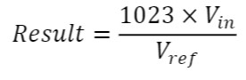
Given the specifications of the Arduino Nano Every, the readings from an analog pin using analogRead() can take on integer values between 0 and 1023, based on the equation below. Note that in this equation, Vin is the voltage input to the analog pin (the output of the voltage divider circuit), Vref is the voltage reference (measured to be around 5 V), and Result is the number that the Arduino reads after an analogRead() function call is performed in the code.
Under normal lighting conditions, the Arduino serial monitor displayed values of around 650 for one of the analog pins connected to a photoresistor. With a flashlight placed around 60 cm away from the photoresistor, that number jumped to 900. With dark surroundings, the number plummeted to around 40.
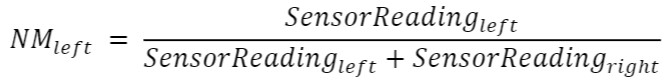
To determine which direction the robot should turn, a Normalized (Differential) Measurement (NM) was used. This equation for the left sensor can be found below, but a similar equation is used for the right sensor. This formula can be understood to yield the relative magnitude of one sensor reading compared to the other. For example, an NM_left reading of 0.5 means that the left sensor's reading is exactly equivalent to the right sensor's reading, an NM_left reading of 0.25 means that the left sensor's reading is lower than the right sensor's reading, and an NM_left reading of 0.75 means that the left sensor's reading is higher than the right sensor's reading. Note that we can see that the sum of NM_left and NM_right should sum up to be 1. In the context of this lab, a higher NM_left reading means that the left photoresistor senses a brighter light than the right.
Some values of NM that I measured are pictured below.
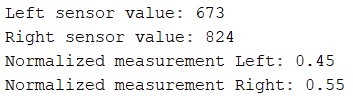
I had light shining brighter on the right side of the robot, which is why I had higher analog values read from the associated pin as well as a higher NM_right value.
Next Steps
In future labs, I will be writing more advanced Arduino code to use the values obtained from the photoresistor circuits to make the robot turn and move towards the brightest light source in the vicinity.