Lab 4
Objective
This lab was split in two parts. In the first part, the robot activated after a specific frequency was detected and turned in place detecting obstacles. In the second part, I turned the robot into a light-following, obstacle-detecting robot.
Materials
- (1) robot from lab 3, sans the non-functional filters
- (1) HC-SR04 Ultrasonic Sensor
- (4) M-M jumper wires
Process
Part 1
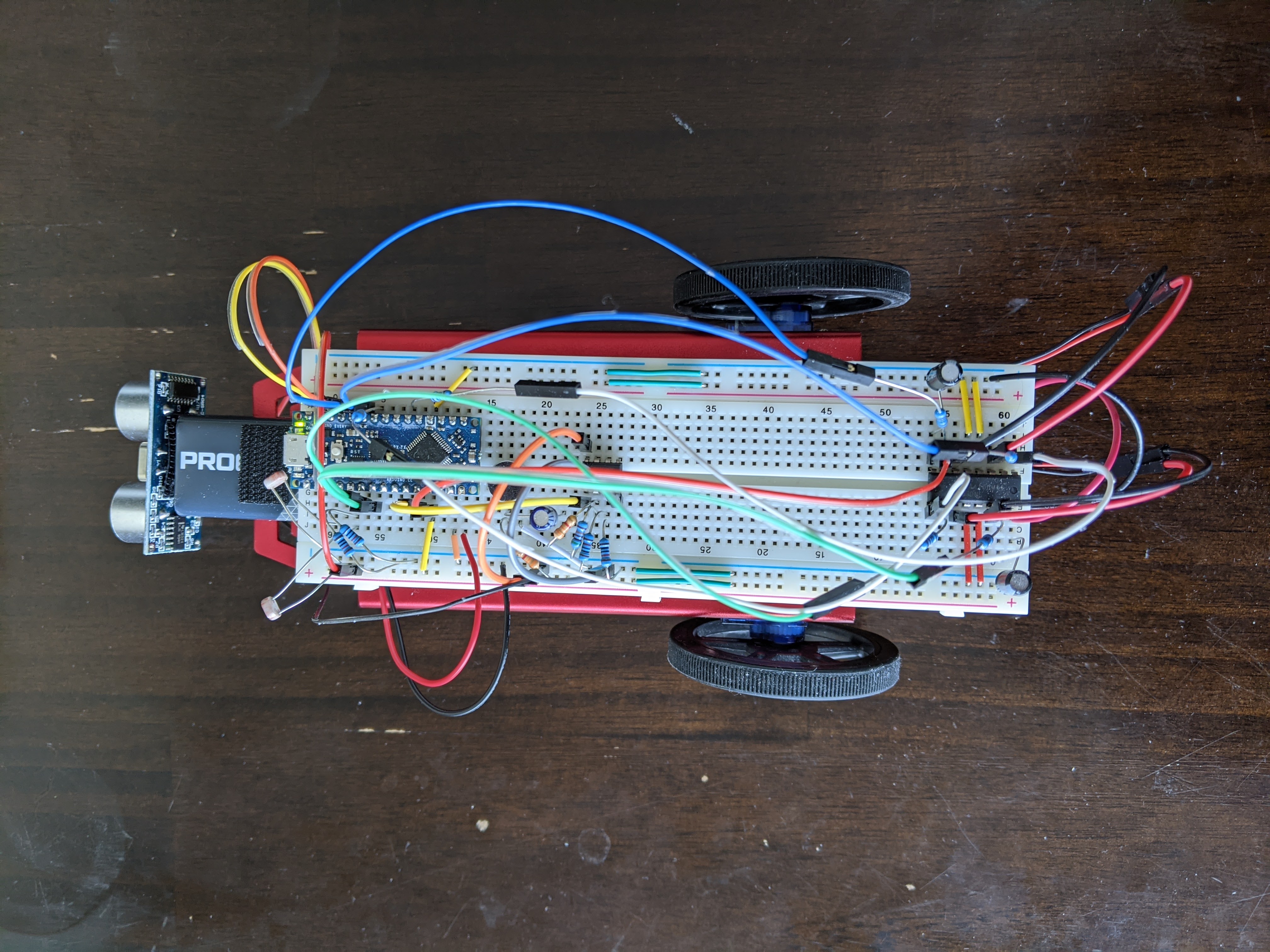
First, I removed the filters from the last lab because the measured frequency response was far from ideal. I also added the ultrasonic sensor after shifting some existing parts around. Finally, I changed the pins I was using for PWM to the motors to D3 (PF5) and D6 (PF4) on the Nano to avoid issues with the timers since I was using the TCA timer to collect audio samples for the Fourier analysis. An image of the result is shown below.
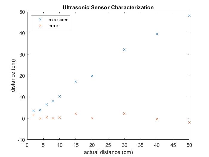
I then wrote code for and characterized the ultrasonic sensor, and plotted the measured distance and error versus actual distance in the graph below.
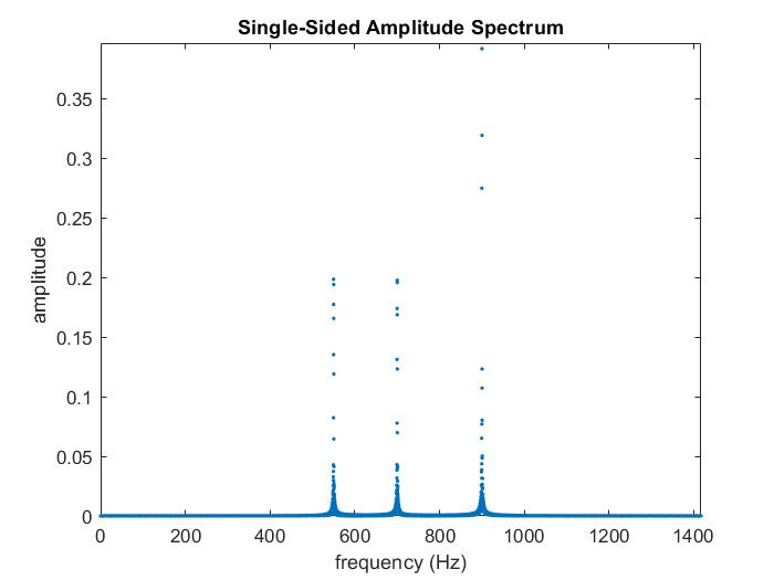
The demonstration for this part of the lab required that the robot starts moving after a 550 Hz tone is detected. I first used MATLAB to plot the spectrum of notes contained in the sound file that was provided to us. The audio file and the frequency spectrum of the audio file are provided below.
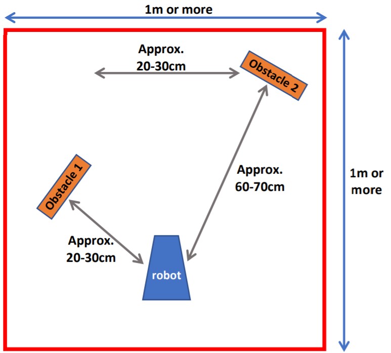
After the 550 Hz tone is detected, the robot turns in place and begins detecting obstacles that are placed in the configuration below. The onboard LED lights up when it detects an obstacle.
A video demonstrating the everything for this part of the lab is viewable below.
Part 2
For this part of the lab, the robot navigates in the obstacle course pictured below, lured by a flashlight.
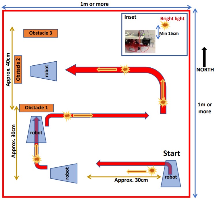
In words, along with LED statuses at each step:
- The robot will be motionless with the LED OFF at the start.
- The robot will be lured left with a flashlight, then right towards obstacle 1. From the moment that it detects obstacle 1, the LED will be ON. When it is within 5 cm of obstacle 1, it will stop moving.
- At this point, the robot will refuse to turn left even though it is being lured. It will only move when it is lured to the right; then the LED will turn OFF.
- The robot will be lured towards obstacle 2. When it detects obstacle 2 at a distance of 30 cm, the LED will be ON.
- When the robot is within 5 cm of obstacle 2, it will stop moving and its LED will be OFF.
- The robot will be lured to turn towards obstacle 1, and its LED will be ON. When the robot is within 5 cm of obstacle 1, it will stop moving.
- The robot will be lured to turn and move towards obstacle 3, and its LED will be OFF.
- When the robot is within 5 cm of obstacle 3, it will stop moving and its LED will be ON.
A video demonstrating the everything for this part of the lab is viewable below.
This concludes lab 4, the final lab of the semester.
Reflection
Overall, I think this class and the labs were a good culmination of everything I learned in previous classes, such as analog circuitry and signal analysis. I also learned a lot because I had to be creative with the code, since I wasn't allowed to use certain libraries or functions like delay() or attachInterrupt(). It was a little frustrating sometimes when things didn't work the way they were supposed to, like in lab 3 with the filters, but I think it was an inevitable but valuable part of the engineering design process and experience.