Lab 2
Objective
The objective of this lab was to integrate what was done in lab 1 (with the photoresistor circuits) with motors in order to actuate the robot and turn it into a full-fledged light-following robot.
Materials
- (1) robot from lab 1
- (1) L293D H-bridge
- (2) 1 uF capacitors
- (6) 1 kOhm resistors
- (6) M-F jumper wires
- (1) M-M jumper wire
Process
Hardware
In order to actuate the motors, the L293D H-bridge chip was used. This IC is capable of controlling up to two motors at the same time, which was perfect for my application.
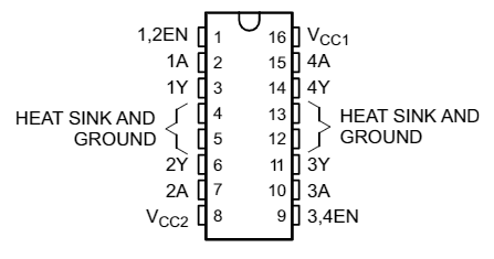
With the H-bridge pinout as pictured above, I connected pin 1, pin 2, and pin 7 to the Arduino to control the left motor. To control the speed of the motor, the enable pin (pin 1) for this motor was connected to a PWM-capable pin on the Arduino. The other two pins were simply connected to two digital pins. A similar setup was done for the right motor, this time with pin 9, pin 10, and pin 15. Pins 3 and 6, and 11 and 14, were outputs of the H-bridge connected to the left and right motors respectively. VCC1 (pin 16) needed a 5 V supply for internal logic, so this was connected to the 5 V output pin on the Arduino. VCC2 (pin 8) is used to power the motor drivers, and this was connected to the 4.5 V AA battery pack on the robot.
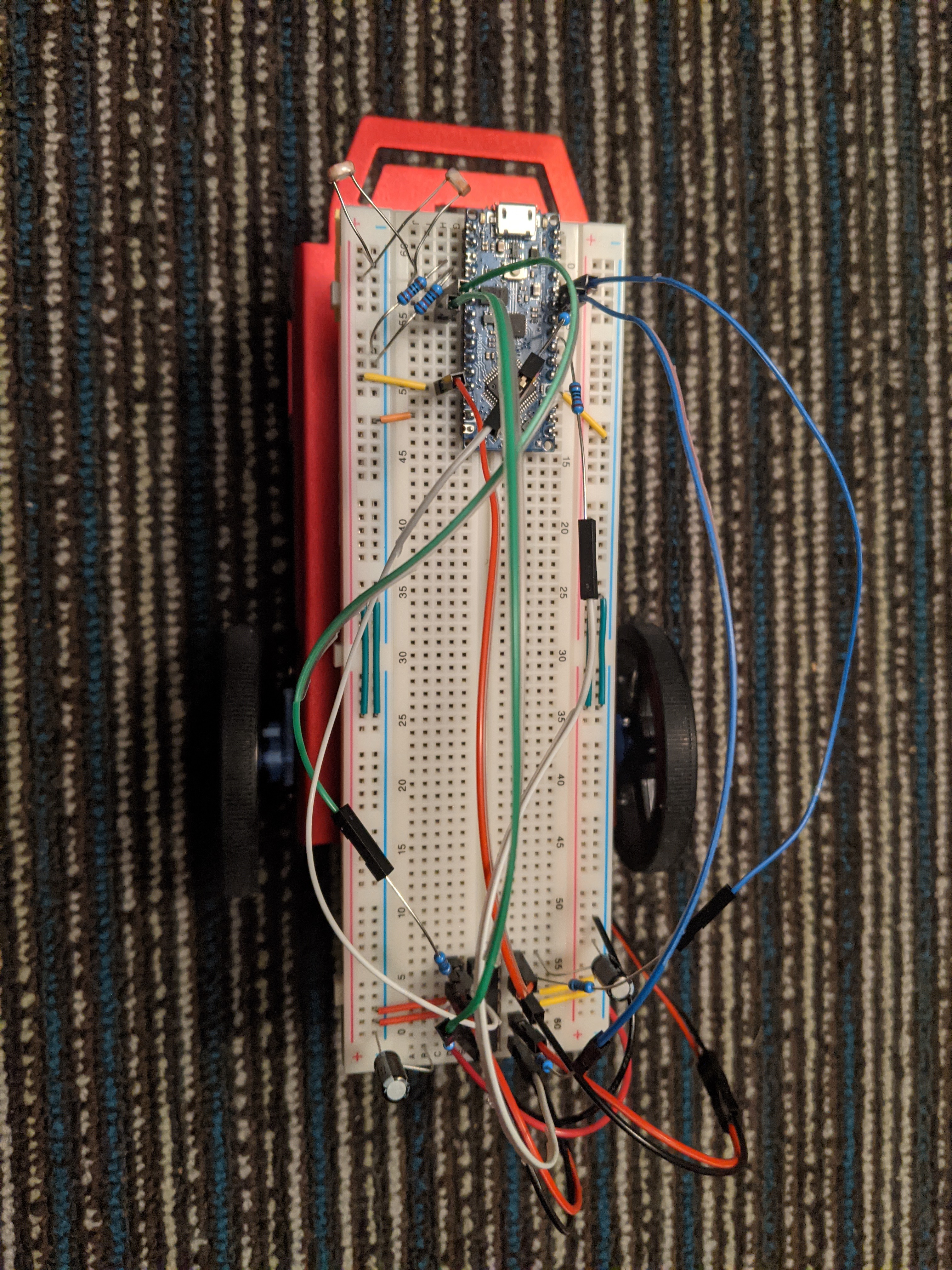
Several components were added to the H-bridge circuit to protect the chip. I connected two 1 uF decoupling capacitors (one between VCC1 and ground, and one between VCC2 and ground) to protect the H-bridge from any voltage fluctuations coming from connecting/disconnecting from power and from within the H-bridge or in the photoresistor circuit which could affect other parts of the circuit, since so much is interconnected. I also connected a 1 kOhm resistor in series between all of the H-bridge pins that connect to the Arduino (a total of six). These will act to limit the current drawn from the H-bridge whenever the Arduino pulls a pin high, or if there is any back-EMF current created by the spinning motors.
I also connected a 9 V battery to power the Arduino, so that the robot could be free to move around without being tethered to my laptop.
The final breadboard connections is pictured below (without the 9 V battery connected).
Software
The code for this lab was written in increments.
First, I wanted to check the functionality of the H-bridge, so I wrote some code that would move the motors in a specific manner, for a predetermined period of time (without using the delay() function!). In particular, it would move both motors forward for one second, both backward for one second, in different directions for one second, in the "other" different direction for one second, and finally stop. The result is shown below.
Next, I needed to calibrate the motors. Without calibration, the motors spun at different speeds, so even though I sent the same PWM values to the motors, the robot did not travel in a straight direction. A demonstration is shown below.
Calibration of the motors was done with both slow and medium speeds, though only the result from calibrating at medium speed is shown below.
Finally, it was time to write the code that would put everything together, i.e. move the robot based on different lighting conditions. There were several cases to consider in this part. Under normal lighting conditions, the robot would spin around, not knowing where to go, with the onboard LED flashing on for 500 ms and off for 500 ms. When brighter light (say, from a flashlight) hit the robot on one side, the LED would turn off, and the robot would turn towards the light and travel towards it. If the light was removed, then the robot would go back to flashing the LED and turning in circles.
For these cases, I used a combination of raw values from analogRead() as well as Normalized (Differential) Measurement (NM) values and established threshold values for each of them. (A combination had to be used because whether the robot was under normal lighting conditions or detected a light shining in front of it, the NM values for left and right photoresistors would be balanced.) At the beginning of the code, I measured and stored the normal lighting conditions. The code would continuously check the current lighting conditions and compare that to that stored value. If the difference wasn't large enough to matter (i.e. under a threshold value), the robot would toggle the LED and spin in circles. However, if it detected brighter light than normal, it compares the NM values for left and right to determine whether it should turn left or right. If the difference between the NM values for the left and right was under a threshold value (different from the threshold value used previously) and the robot was still detecting more than normal light, it would travel forward (towards the light).
Final Result
Next Steps
This concludes the light-following robot portion of the course for a while. In Lab 3, I will be implementing and testing a bandpass filter that will be used in my robot for Lab 4.