Lab 1: Setting up the IDE and testing a few board functions.
Blink and you'll miss it
Upload code to the Artemis to get it to blink.
After installing the board data onto the Arduino IDE, arbitrary code could then be uploaded to the board. This was tested using the example code "Blink It Up." After uploading, the board began to blink on and off as expected. The video below shows the board blinking its blue light, the lowest one of the lights.
You can't be serial
Tell the artemis to transmit some data to the serial monitor.
The example code "Example04_Serial" was uploaded to the board, with the expectation that it would print a certain message to the serial monitor, then prompt for a string which it would then print back. The message did print, and the board return the message sent to it as expected. The picture below is the output to the serial monitor.

Packing heat
Have the artemis give a temperature reading, and test it by raising and lowering the temperature.
The "Example02_AnalogWrite" code was uploaded to the board to test the temperature sensor. The board continuously plotted the temperature onto the serial plotter. The reading from the temperature sensor increased in response to squeezing the board with a hand, and decreased after taking the hand away. The image below is a plot of the temperature over time, represented by the green line, with different points of time where the board had been squeezed.

Mic work, mic not
Conclude with a test of the microphone of the board.
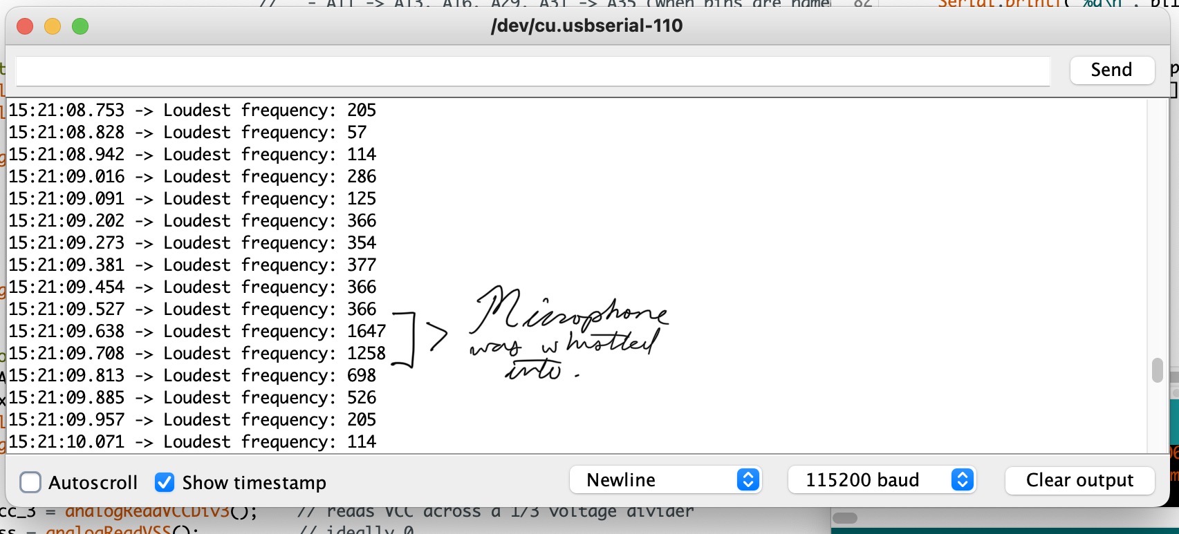
For this last test, the code "Example1_MicrophoneOutput" was uploaded to the board, which was expected to repeatedly display the highest frequency note heard by the microphone in a short sampling period. The board worked as expected, and the result given to the serial monitor is shown below. At a certain point, the microphone was whistled into, producing a high frequency note.

This is it for lab 1. If you want to go back to the homepage, press the button below. But no pressure.