Lab 5: Powering and Controlling the DC Motors.
Power Couple
Plan to connect the Arduino and a power supply to drive DC motors using a motor driver.
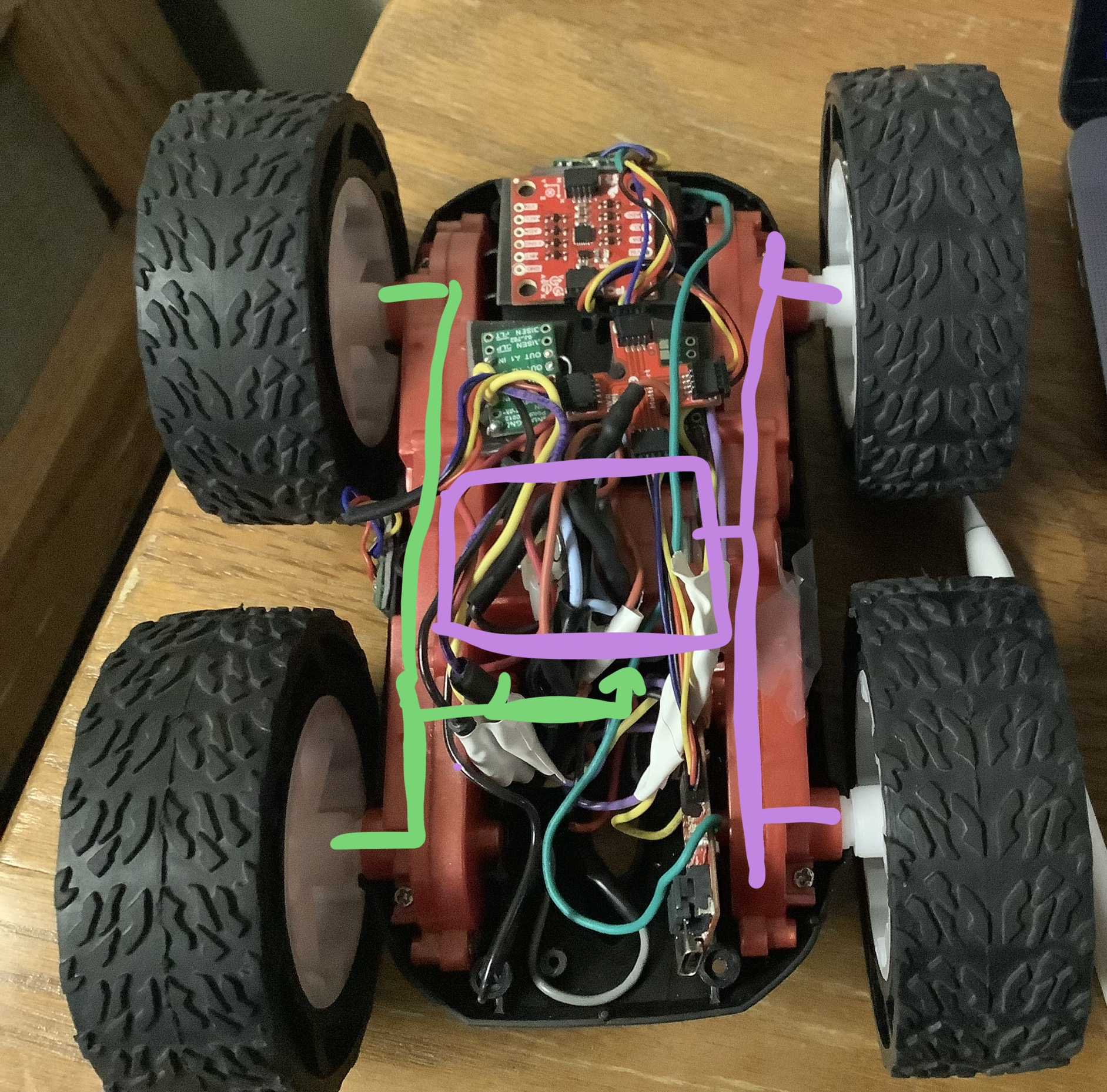
The car has two motors, which each drive two wheels on either side. The motors are placed vertically in the center of the car.
For this purpose, a motor driver was used to power each motor, since the Artemis alone cannot supply the necessary current, which is around 1A. The motor drivers took two PWMs (pulse-width modulated signals) as input, and drove a motor based on the two inputs, having speed-regulated forward and reverse functionality, as well as coast and brake functions. The table below outlines the control capability of the driver, with information from the class lecture slides (6-Actuators).
| xIN1 | xIN2 | Action |
|---|---|---|
| 0 | 0 | Neutral |
| 0 | 1 | Reverse |
| 1 | 0 | Forward |
| 1 | 1 | Brake |
The motor drivers we're using are capable of driving two motors on a single chip using two different channels. However, to increase the current available to drive each motor, the driver will power a single motor, with the inputs/outputs for each channel shorted. This is safe, considering that the timing circuitry is shared between the two chips, and wouldn't cause interference, compared to combining different drivers that may have slightly different timing. The diagram below shows the connections made to control each motor and combine channels A and B.
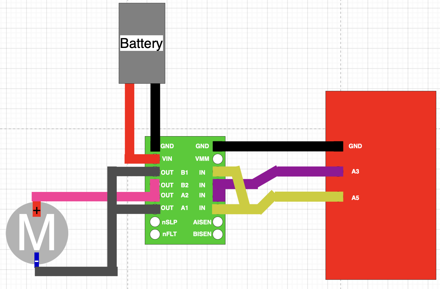
The same connections will be repeated using the second motor and the second motor driver, except using different pins. A3/A5 will be used for one motor, and A9/A11 for the other. Several other pins could have been used, as long as they were able to output PWM signals.
Seperate batteries will be used for the Artemis and the motors. The high amount of noise created by the motors may interfere with the Artemis, so a seperation in power supply will eliminate the motors' side effects.
Current Affairs
Controlling the motors with the Artemis.
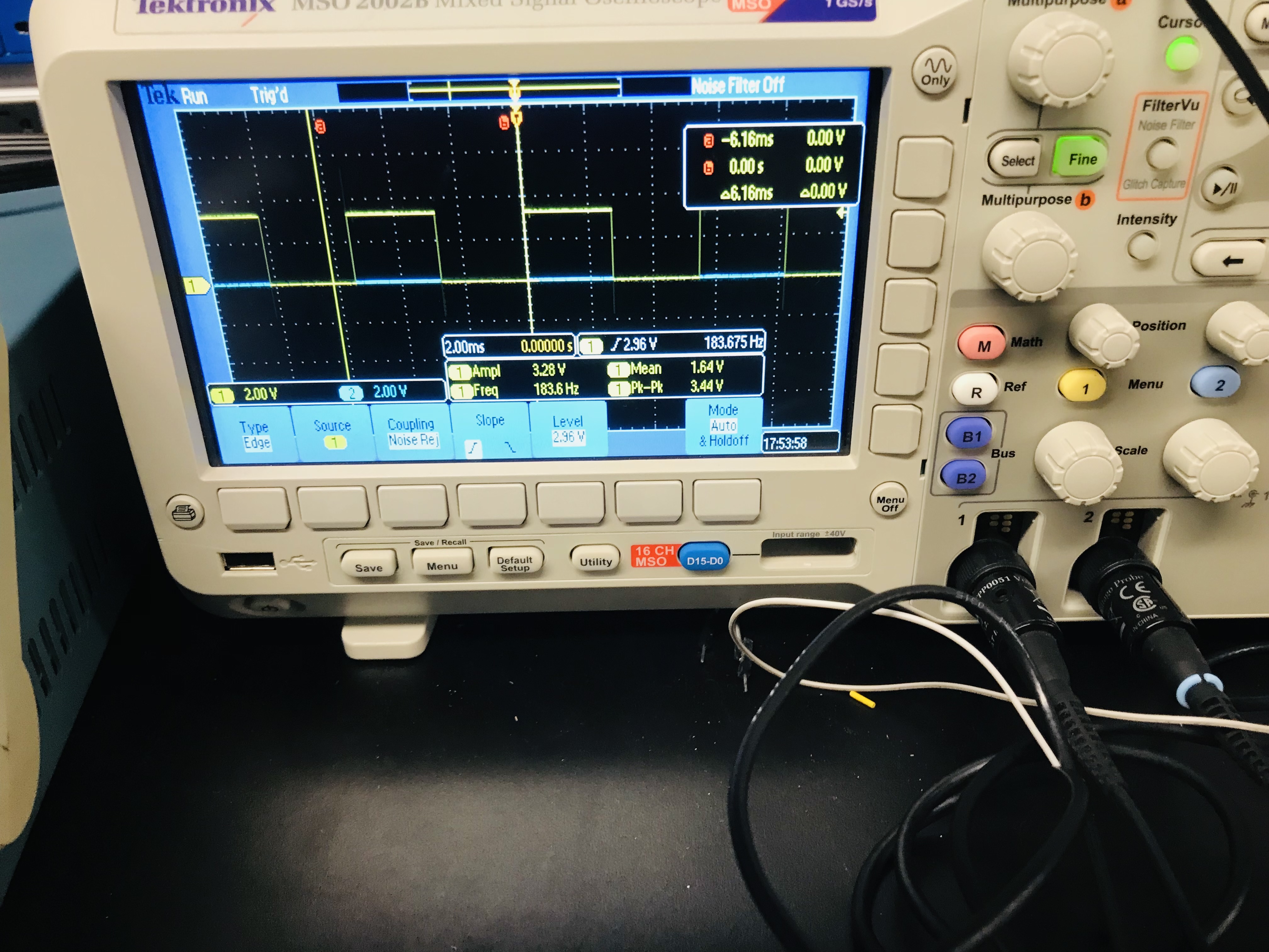
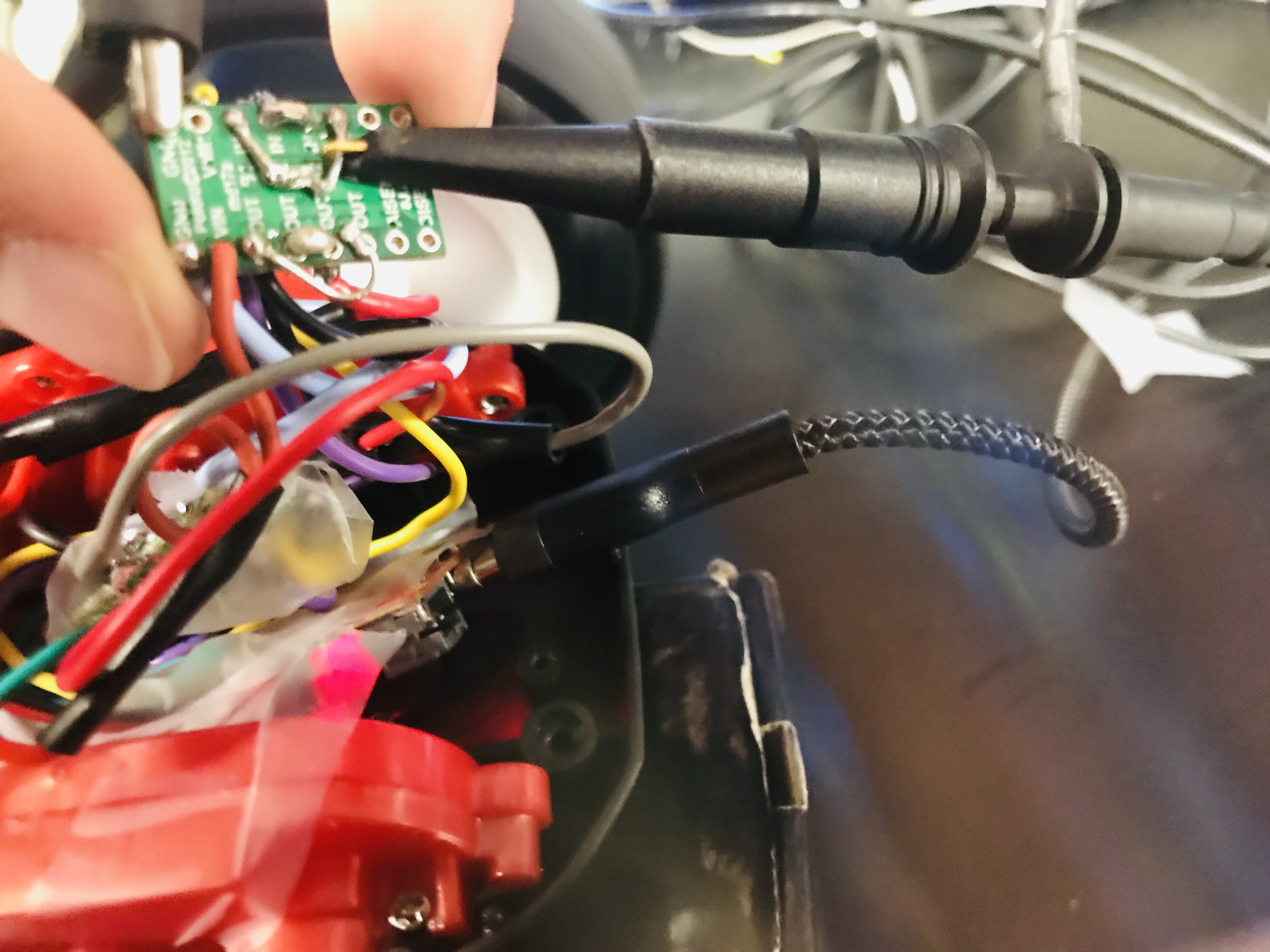
The motor drivers, motors, and Artemis were connected in the manner described above. To demonstrate the ability of the Artemis to control the motors, a PWM signal was sent to the board and the signal was observed on an oscilloscope.
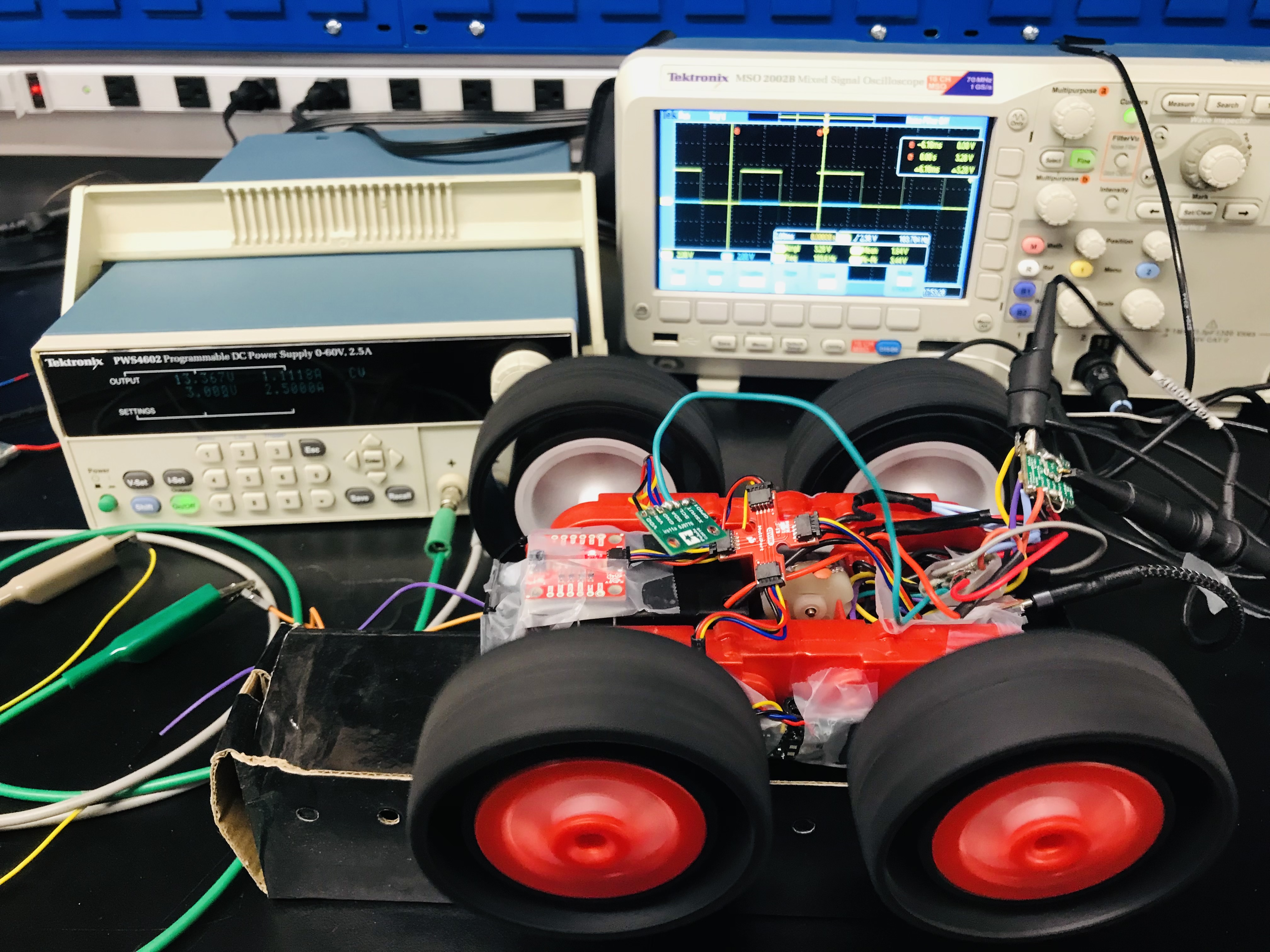
Here is a closeup of the oscilloscope reading and the connecions made on the Artemis.
The motor was then connected. Just to test the motors, the following code was used to write to the motors using an input from the Serial monitor.
Code was written to control the motors wirelessly. A Jupyter notebook was created to send the speed setting to the board, which would then write to the motors. The following video was taken to demonstrate control of the motors wirelessly and in both directions.
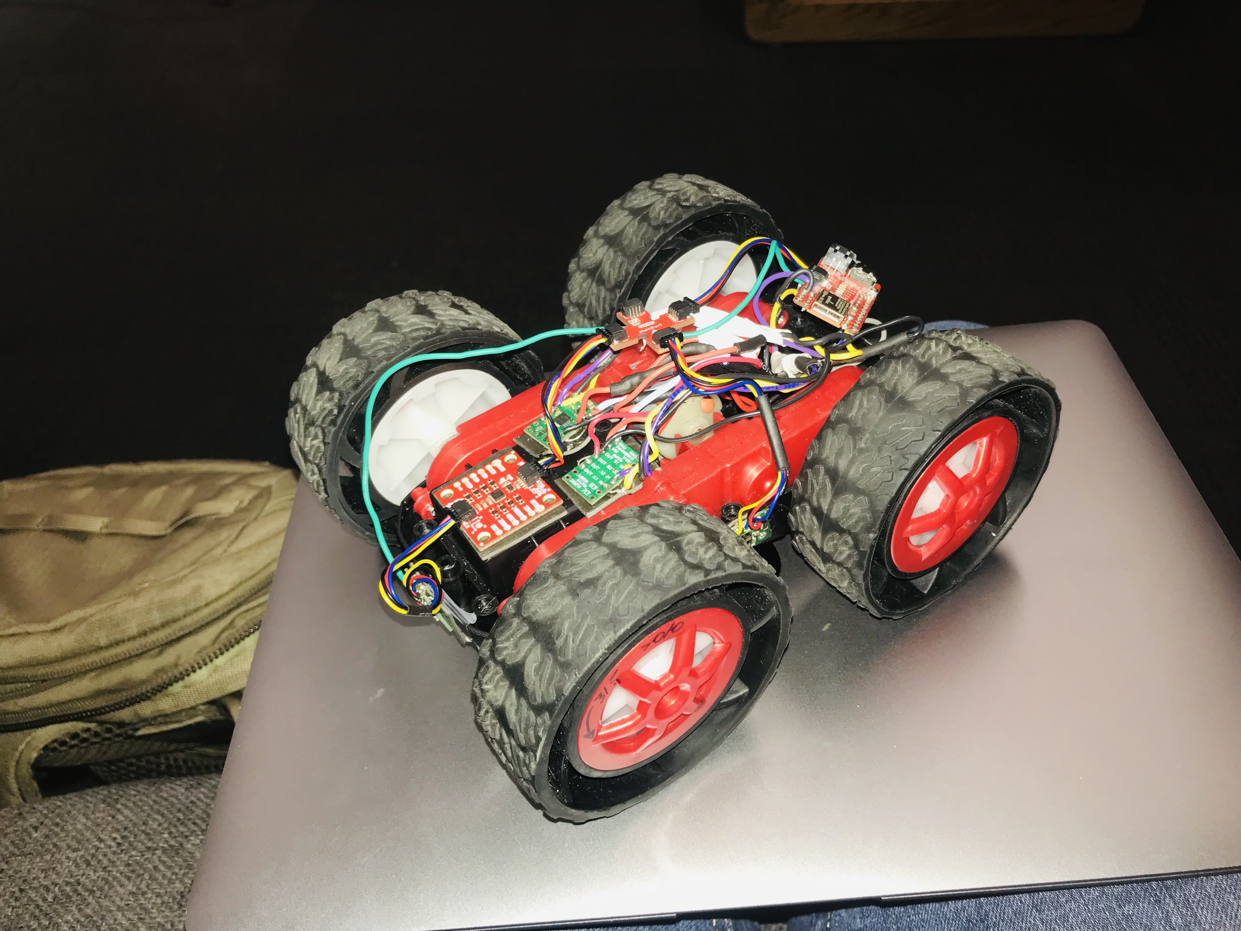
I then installed both motors. The video below is a demo of the motors running together.
Below is all the parts installed on the motor. The motor battery is installed underneath and the lead is passed through.
It's about drive it's about power
Open loop control of the DC motors.
Before shooting the video above I did a simple attempt at calibration. I set the speeds of the motors differently such that it would go straight after an initial "rev up time." This was due to the fact that the left motor had a tendency to "stutter", or to hesitate to start immediately. The video below shows what I mean.
This problem was solved by increasing the frequency of the PWM signal coming from the Artemis. It seems that the lower frequency signal send a signal too "jittery" to appear like a smooth analog signal. The motors now appear to move smoothly, although they now emit a high pitched whine as they operate. In addition, ramping was implemented; the speed will write to the motors slowly over time. Ex, if starting from a coasting position, and the desired value to output is 150, try increasing in increments of 10 over time, until you reach the desired speed. This in combination with the increase in frequency prevented the stuttering issue, and allowed the robot to move straight as shown below.
The gradual speed increases were done by the code below.
How low can you go
Discussion on the lower limits of the PWM.
For future reference, the lowest limit of the motor speed was found.
| Floor? | Min fwd duty cycle, /256 | Min rev duty cycle /256 |
|---|---|---|
| Left motor off floor | 75 | 80 |
| Right motor off floor | 64 | 70 |
| Left motor on floor | 130 | 130 |
| Right motor on floor | 135 | 125 |
The lower limit on the motors is important to know when more precise control is needed. The motors must be driven at least a little above the "on floor" values to ensure some kind of motion. Battery depletion may have the effect of increasing the needed duty cycle for motion.
Open to suggestions
Demonstration of open loop control
The following video is a demonstration of open loop control of the robot. It is designed to move forward, make a turn, then move backward. It is connected to a power cord since there was a broken lead on the Artemis battery, but the cord didn't interfere with operation.
This is the end of reporting for lab 5. In the next lab, some PID control will be implemented, which will regulate the speed of the motors, a step towards autonomous operation.