Ryan's ECE 4960 Site
Lab 4: Characterize Your Car
Prelab
The goal of the prelab was to prepare the Artemis and sensor setup we created in the previous lab to be used in this lab to help take measurements. To do this, we had to run this setup from a battery instead of tethering the setup to our computer. This invovled modifying the 600mAh battery that came with the robot to have a 2mm JST pin so it could connect to the Artemis. I was successfully able to do this and my Artemis and sensor array could be powered by the battery.
Testing!
Dimensions
I chose to measure the dimensions of the car because it would be very important to know
the length, width, height, and wheel diameter of the car if we have to model it in simulations or have to map the car's position
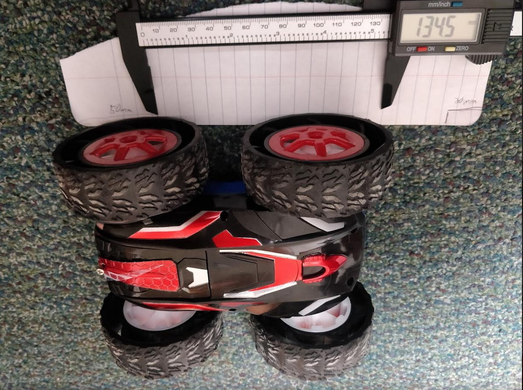
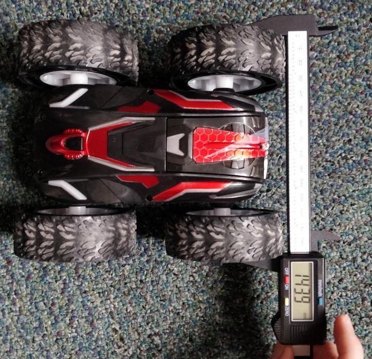
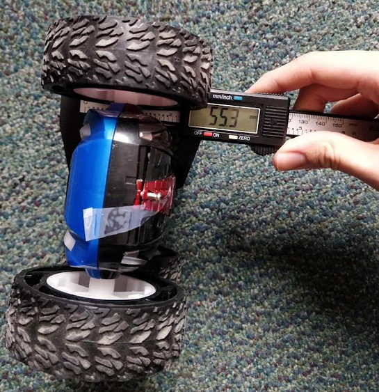
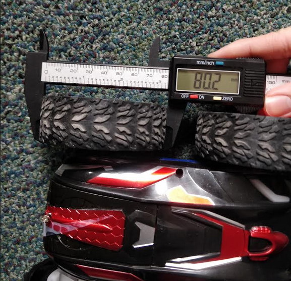
in the future. It is also a relatively simple measurement to do. To do this, I used digital calipers to
take these measurements which are in the table below. (Note: the caliper only went up to 150mm, so for the length, I
added 50mm on the paper).
| Length | Width | Chasis Height | Wheel Diameter |
|---|---|---|---|
| 184.5 mm | 143.9 mm | 55.3 mm | 80.2 mm |
Battery Life
I chose to measure the battery life because this gives a rough idea of the current battery capacity based on how much time has passed.
This is useful because it tells you how much longer the robot can last. It is especially important
with the motors, because they could slow down as the battery voltage decreases as the battery capacity runs down, which
could be an important consideration.
For example, if you know the battery life is about 10 minutes and 9 minutes have already passed, you might want to consider
swapping the battery before doing any stunts that rely on fast motor speeds.
To test this, I installed a fresh battery into my robot had the robot rotate in place at full speed until it stopped moving while timing
it on a smartphone. I ran 3 tests, with the results summarized in the table below. (Note: that the last 2 tests were done on carpet while
the first test was done on a smooth floor, which could explain for the shorter battery lives.)
(Collaborator credit: Minjung Kwon helped with this test)
| Test 1 | Test 2 | Test 3 | Average |
|---|---|---|---|
| 473 s | 389 s | 423 s | 431 s |
Charge Time
I chose to measure the battery charge time using the charger that came with the remote-controlled car because
it would allow me to determine the feasability of running tests outside of the lab where there is a surplus
of pre-charged batteries.
I initially tried to test this by taking an empty battery (from the above battery life test) and charging it while
timing it on a smartphone. After noticing that it was still not fully charged after a very long period of time, I decided
to switch my approach to measuring the current output of the battery charger with my multimeter and calculating the
charge time based on this. I found the current output to be exactly 50mA, so to charge the 850mAh battery from fully
empty, it would take about 17 hours. Based on this very long charge time and the short battery life, I determined that
it isn't very feasable to run tests outside of lab due to the amount of time it'd take to charge the battery between tests.
Speed
I chose to measure speed because it is very likely that it will be an important factor for our robots in this class
considering the class name Fast Robots. Knowing the speeds would also likely be useful if we do simulations of the robot in the
future.
I first tested this by measuring 6 feet (1.83 meters) on the ground marked with tape and driving the robot at full speed through this length
while taking a recording of it on a smartphone. Using the video, I figured out how long it took to travel the 1.83 meters, and
used that to calculate the speed. We ran 3 tests with the results summarized in the table below:
(Collaborator credit: Minjung Kwon)
| Test 1 | Test 2 | Test 3 | Average |
|---|---|---|---|
| 3.45 m/s | 3.66 m/s | 3.89 m/s | 3.67 m/s |
I next tried to use the ToF sensors to measure the speed. This involved combining the Bluetooth and ToF code and reading the data using the Jupyter Notebook we used in Lab 2:
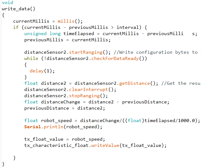
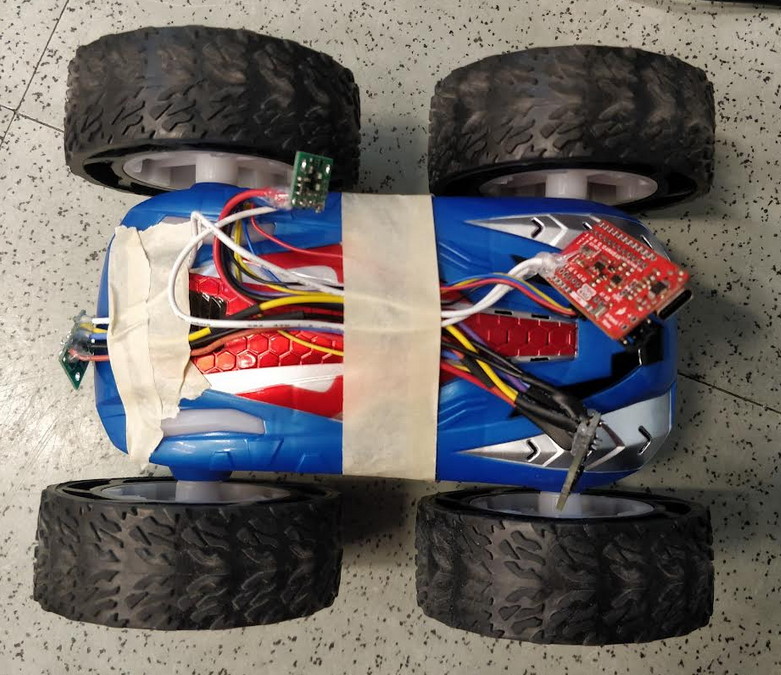
I ran 3 tests using this, which are summarized in the data below. The values differ substantially from the above values and are also much lower than expected (except for one), which indicate that the data is wrong. The variation is also much greater. After looking at the code, I believe that the issue is from the "interval" variable being too large.
| Test 1 | Test 2 | Test 3 | Average |
|---|---|---|---|
| 0.64 m/s | 3.83 m/s | 0.54 m/s | 1.67 m/s |
Stunts
I chose to do stunts for this lab because it will be an important part of the robot in future labs and I'd like to
get started with it early so I can possibly make design decisions on the robot based on the stunts early on. Doing stunts also
allows me to push the robot to its limits, which gives me a better idea of what I'm working with.
** Drifting **
The main stunt I wanted to do was the elusive drifting. Since the TAs mentioned that it would be a very difficult stunt to
perform, I thought it would be an interesting challenge. After several tries I determined that the best sequence was this:
Motors forward at full speed > Turn off motors > Short right turn to initialize drift > Even shorter left turn to prevent the
robot from losing control and spinning out
This is a very difficult sequence to do by hand due to the quick reaction speeds needed, but it should be much easier to
do once we connect the Artemis and motor drivers to control this sequence.
Here is a video showing this, where the robot drifted for about 1.5 feet.