Ryan's ECE 4960 Site
Lab 5
This lab was dedicated to open loop control of our robots using the Artemis microcontroller and motor drivers.
Prelab
The motor drivers are capable of driving two motors each, but we are parallel coupling them for increased power and speed. This is done by shorting a few connections on the motor drivers together. To control these motor drivers, I decided to use Artemis pins 4 and A5 to control one motor, and pins A15 and A16 to control the second motor. I chose these pins specifically because they are capable of generating PWM signals. Additionally, I decided that it'd use a separate battery to power the motors. One reason for this is to reduce possible power supply noise to the Artemis microcontroller, which is more sensitive to this. Another reason is to give the motors more power since the power output is unregulated and there is a bigger battery. I then planned the wiring based on these considerations by drawing the connections on a tablet, which is shown below:
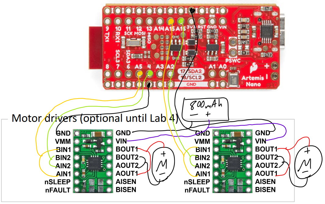
Connecting the Motor Drivers
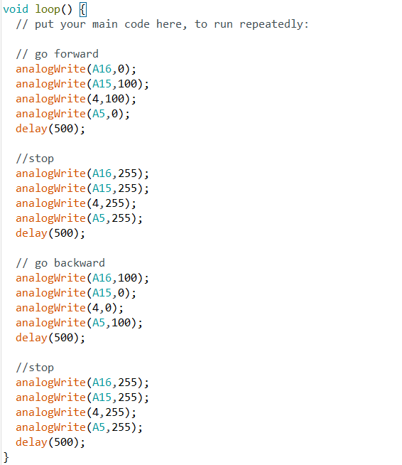
I first soldered one motor driver to the Artemis microcontroller and configured it to be parallel coupled. I then connected the motor driver's VIN to a power supply set to 3.7V, which I thought was reasonable since it is the same as the nominal voltage of the batteries we are using to power the motors. After that, I used analogWrite on the Artemis to send various PWM signals with different duty cycles to the motor drivers and confirmed that they were functioning correctly on the oscilloscope. The code used to do this and pictures of the output are shown below.
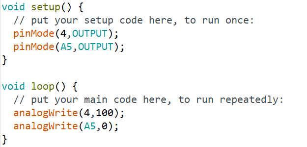
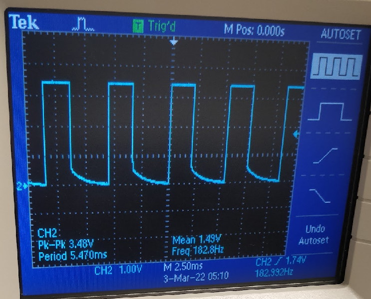
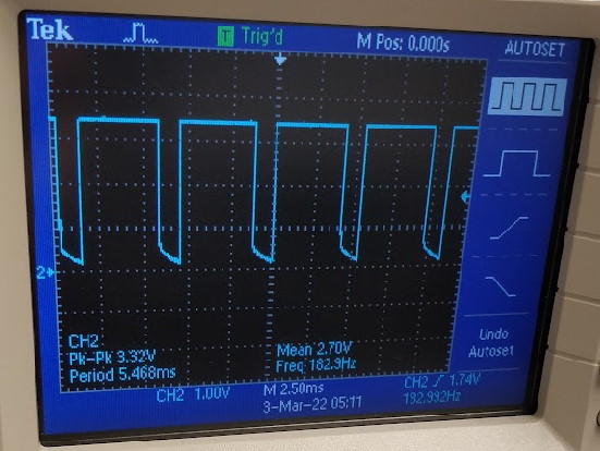
After confirming the wiring worked, I then disassembled the car and took out the default control circuit board. I then soldered my own control circuit to the car's motor and tested it by running the motor in both directions while still connected to the power supply.

After confirming that this worked, I then soldered the original battery leads from the car to the motor driver and confirmed that it worked with an 850mAh battery. Finally, I repeated the above steps for a second motor and motor driver, installed everything into the car's chassis, and connected the car's original 650mAh battery to the Artemis (modified to have a JST plug soldered on).
Controlling the Robot
After finishing the car's motor control circuitry, I began rigorously testing the motors' behavior to characterize it.
I began by trying to find the lower limit of the PWM duty cycle I could send and still have the motor turn on the ground.
After much testing, I found it to be about 30, or about an 11.8% duty cycle.
I then tried to make the robot go in a
straight line and did this by making both motors go forward with roughly the same duty cycle. After much experimenting,
I found that I had to add a calibration factor of about +5 to the PWM of the left motor to keep it straight. A test is
shown below, where it successfully traveled very straight for 6 feet, and then started to veer off to the left (Note:
the tape in the video is longer than 6 feet)
Finally, I ran a test demonstrating successful open loop and untethered control by making the robot go forward, turn left, go forward, and turn right, which is demonstrated in the video below: