
Lab 4(a): Open Loop Control
Objective
To learn about open loop control and implement it on the car. The car will be autonomously controlled through pre-programmed moves that will be executed through the Artemis board and the motor driver.
Materials
- SparkFun RedBoard Artemis Nano
- USB A-to-C cable
- Li-Ion 3.7V 400 or 500mAh battery
- Sparkfun Qwiic motor driver
- R/C stunt car and NiCad battery
- Qwiic connector
- Small screwdrivers (Phillips and flathead)
- (optional) Wirecutter
- (optional) Drill and 1/4 inch drill bit
Procedure
- First, I hookedup the Artemis board and motor driver together using Qwiic connector.
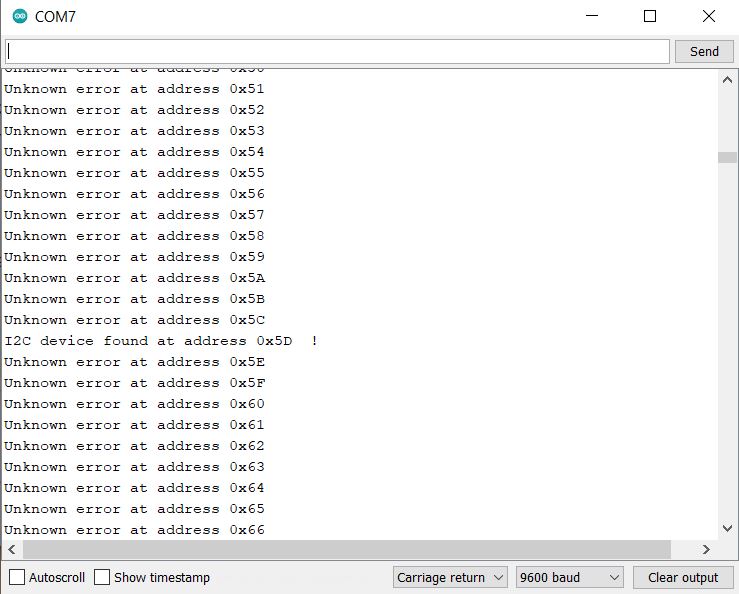
- I ran the given Example1_wire code in Arduino to find I2C device, which came out to be 0x5D. (The file can be found under Files -> Examples -> Wire).
- I unscrewed and removed the shell, battery, control PCB.
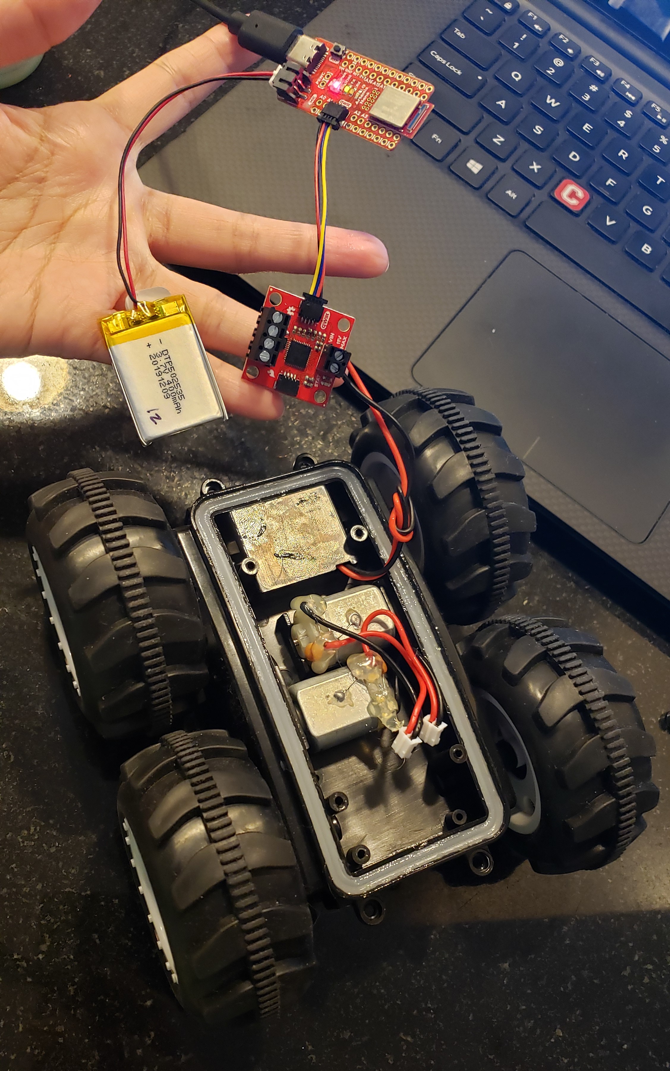
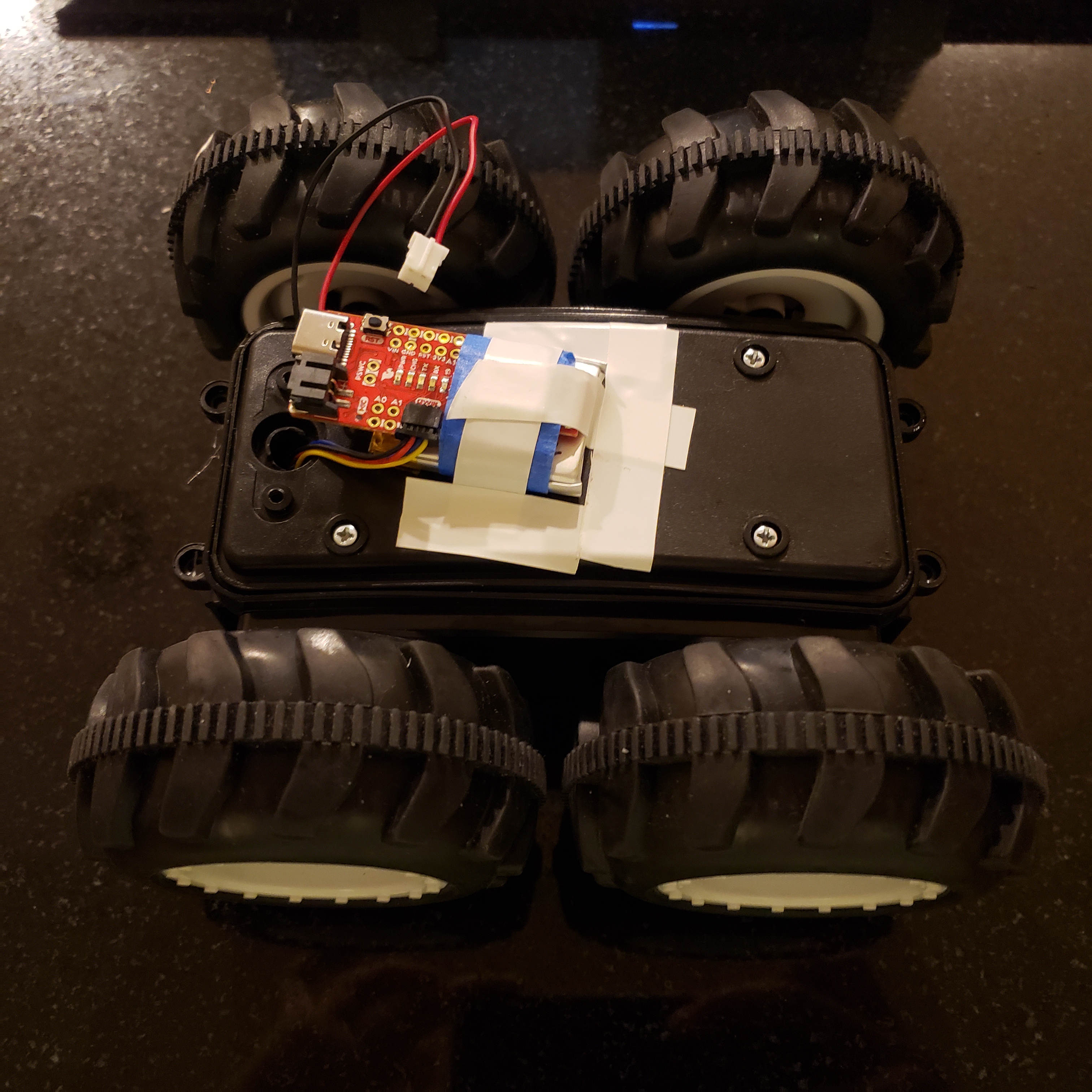
- Then cut the wires from control PCB and the two motors and connected them to the motor driver. Since I didn't own a wirecutter or a wire stripper, I had to strip the wires with scissors, which was a challenge. I also attached the Li-ion battery to the Artemis and connected it to my laptop using USB C connector. But after all the wires are connected, it looks like this:
- In Arduino library manager, I installed Serially Controlled Motor Driver (SCMD) library.
- I used the MotorTest script given in the library (File -> Examples -> Serially Controlled Motor Driver) and edited the code to access the connected I2C device, which was 0x5D (as seen in step 2).

- By running the code, you can see that the motor works!
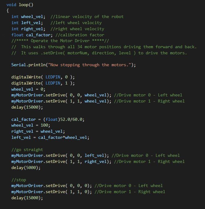
- Since the motors aren't exactly identical, I tested the lower limits for drive strength. The left wheel had lower limit of 60 and the right wheel had lower limit of 52. Since the two wheels have different limits, I calculated a calibration factor. In this calculation, I assumed that the drive strengths are linearly dependent to each other and created a ratio based off of the lower limit. (This may not be an accurate assumption, but seems to work for low/mid speeds.)
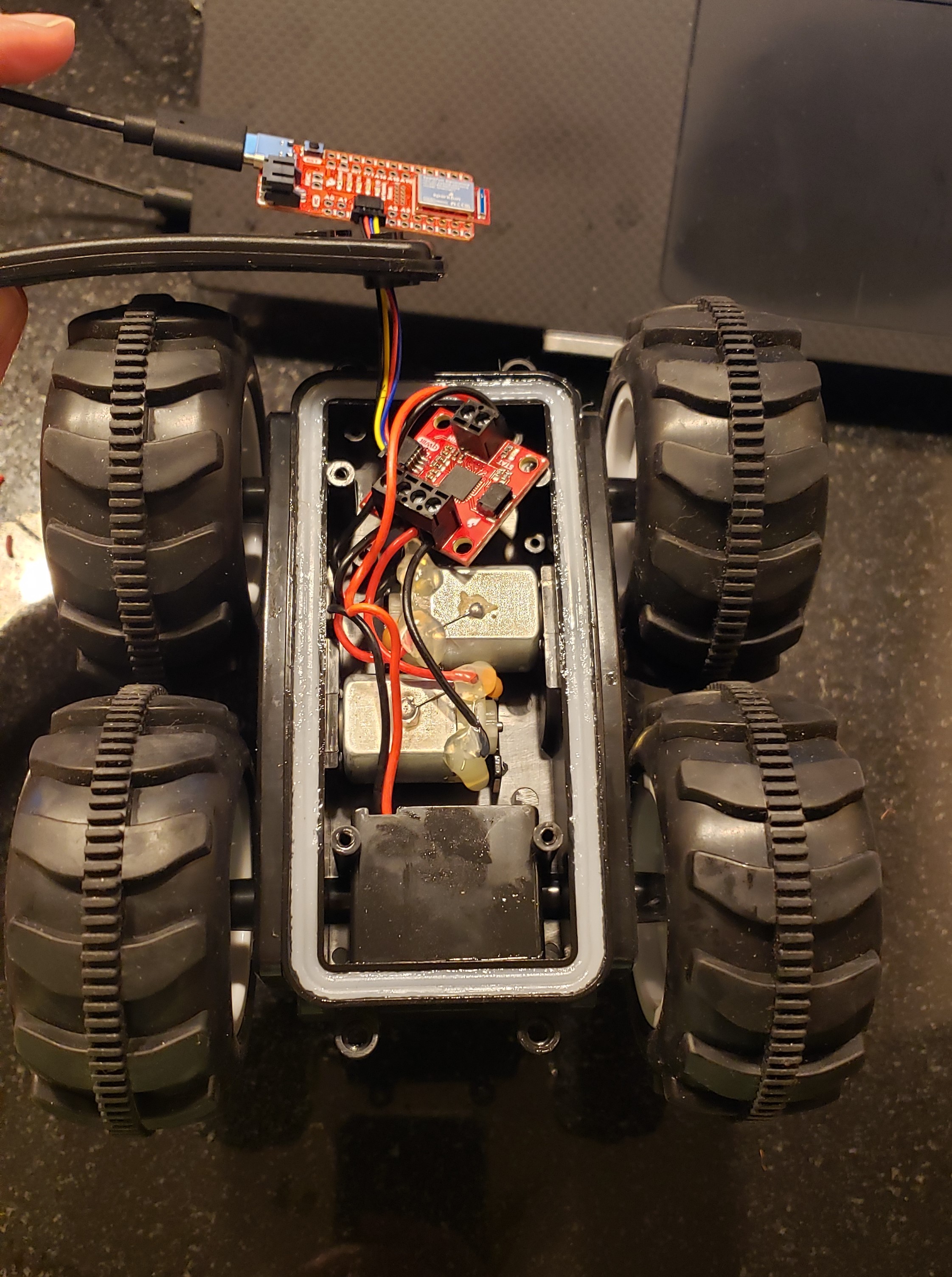
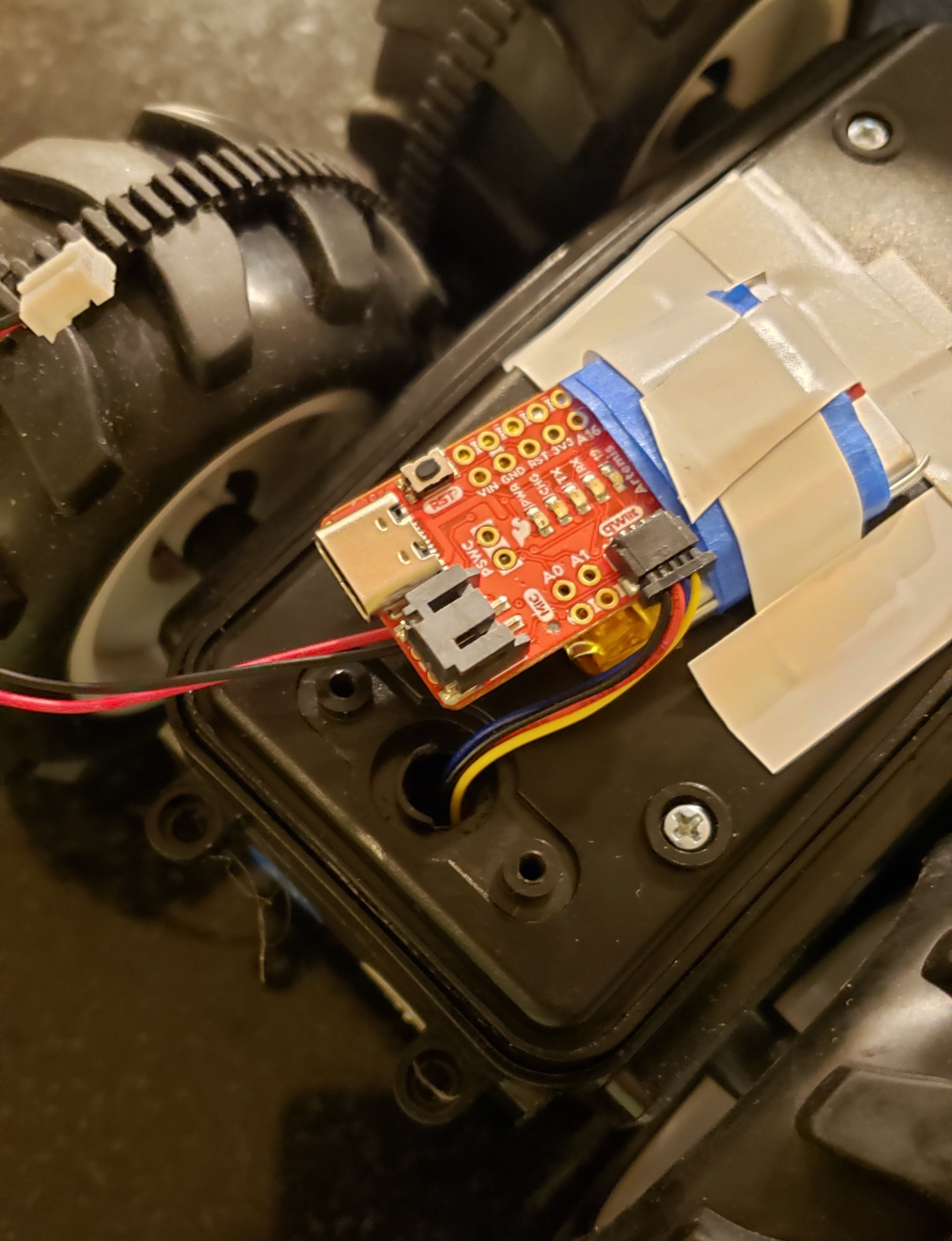
- I assembled my robot and fit the motor driver into the chassis. The Artemis board was wired outside by enlarging the hole on the chassis. I used a quarter inch drill bit.
- I used the code here to make the car move in a straight line. You can also view the script below.
- I also demonstrated an open loop control of the robot by attempting to create a square. Since this is a longer code, here is a link to the code.
This is the fully assembled car! :)
Lab 4(b): Open Loop Control
Objective
To implement open loop control in the simulator by using jupyter lab.
Files
Procedure
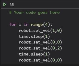
I downloaded the code for lab4 and extracted it to my VM then set up the base code by running ./setup.sh in the terminal. After closing all the terminals, I started the simulator by running lab4-manager in a new terminal. Then, I opened another terminal and changed my directory to the Lab 4 folder where I ran jupyter lab. In the notebook file, lab4.ipynb, I coded an open loop for the robot that would make it move in a square motion:
You can access the Jupyter notebook file here
This is the motion on the simulator:
The code was built through some trial and error. I timed how long it would take the robot to turn 90 degrees at a corner and used that time to make turns in the square. The robot created a square by moving for a equal time at a constant velocity for each side and used the measured turning velocity and time to get the right angle turns.