Lab 6(a): IMU, PID, and Odometry
Objective
Setting up IMU and mounting it on the robot to implement PID control using the IMU.
Materials
- SparkFun RedBoard Artemis Nano
- USB A-to-C cable
- Li-Ion 3.7V 400 or 500mAh battery
- Sparkfun Qwiic motor driver
- R/C stunt car and NiCad battery
- Qwiic connector
- 9-axis IMU
- TOF sensor
Lab Procedure
-
Setting up IMU
- I installed the SparkFun 9DOF IMU Breakout - ICM 20948 - Arduino Library in the Arduino library manager.
- I connected the IMU to the Artemis board using a QWIIC connector.
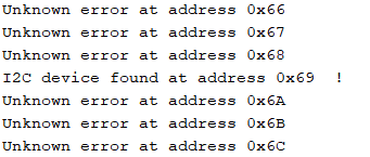
- Using the given Example1_Wire script, I scanned for the sensor and got that the address was at 0x69.
- I also ran the given script, Example1_Basics under File->Examples -> SparkFun_ICM-20948. This allowed me to visualize what sensor values are output from the IMU sensor. I was able to see changes in acceleration when I moved in the x,y, and z direction as specified on the board. I was also able to see changes in roll and pitch of the sensor when I rotated it.

-
Accelerometer
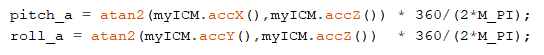
- Accelerometer gives values of acceleration in the x,y,z direction. Using those values, I can calculate the pitch and roll of the sensor.
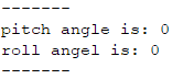
I was able to get pitch and roll angle of 0 on a flat surface.
I was also able to get 90 and -90 degrees on both pitch and roll when I lined up the sensor against a wall.

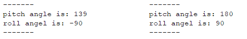
I also tested the accuracy of the accelerometer by measuring the data when its completely flat and when it's against a wall at 90 degrees. The values were -1 to -2 degrees off. -
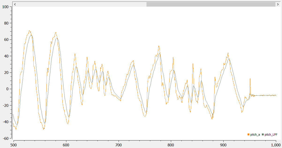
With the power of trial and error, I concluded that alpha value of 0.2 would be best for the low pass filter. In the image below, low pass filter for pitch captures the angles while reducing the noise values.
- Accelerometer gives values of acceleration in the x,y,z direction. Using those values, I can calculate the pitch and roll of the sensor.
-
Gyroscope
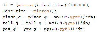
- I calculated roll, pitch and yaw angles from using the data collected from the gyroscope.
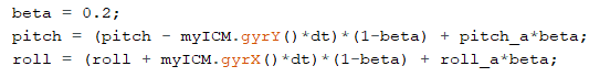
- I compared the pitch from the gyroscope and from the accelerometer with the low pass filter. While gyroscope pitch has more noise compared to the accelerometer pitch, it has a faster response time to the changes in angle.

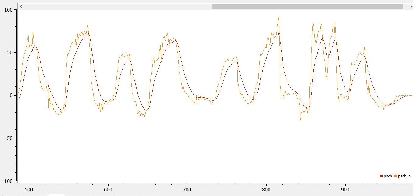
I also compared the roll between the two sensors. Similarly to the pitch, the accelerometer has a slower response compare to the gyroscope roll.
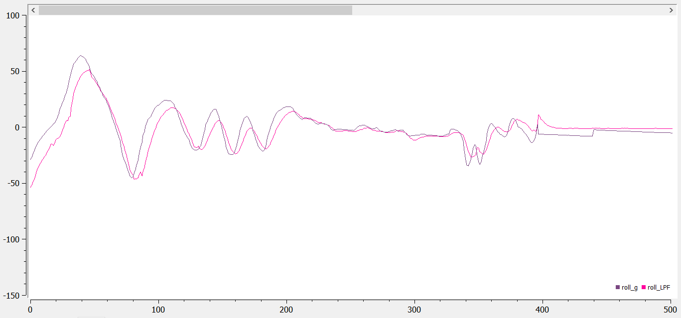
- I used the complimentary filter to estimate the pitch and roll with the given equations. From trial and error, beta = 0.2 seems to produce the best output without significant delay.
-
Magnetometer
- I converted the magnetometer data to yaw angle using these equations.

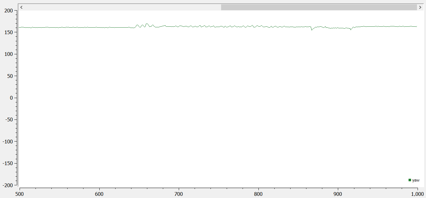
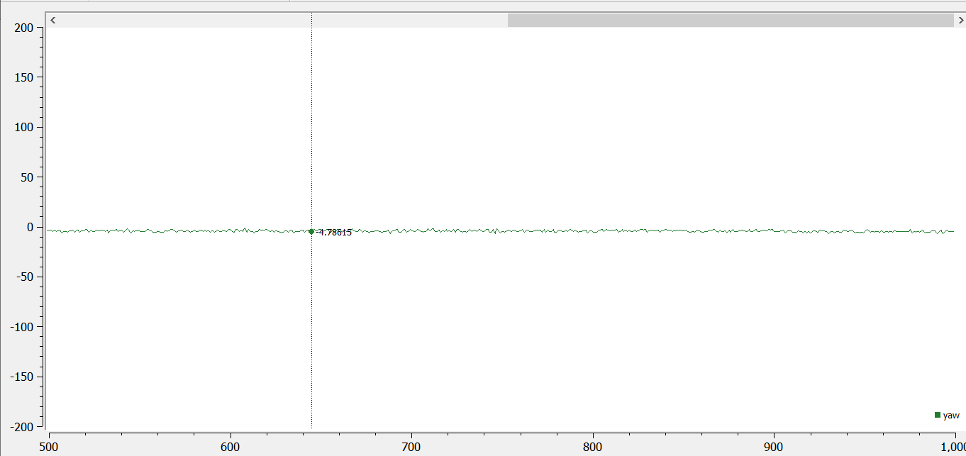
- I tested how robust the yaw angle is to small angle changes as shown below in green. When I moved the sensor, it seemed resilient to small taps and changes in angle.
- Using the magnetometer data, I was able to find north with good accuracy. I checked with a compass on my phone to see the direction of north and it matches the x-axis on the IMU.
- I converted the magnetometer data to yaw angle using these equations.
-
PID Control
-
To test the angular speed of the robot, I wrote the script attached here
and uploaded it to the Artemis board. The script tells the robot to ramp up the motor power from 0 to 255 and then ramp down. While doing so, the robot can send back its sensor information via bluetooth about the gyroscope readings. I had to grease my wheels since it would barely move, but with a little grease, the maximum angular velocity came out to be approximately 1000 rads/s. While watching the robot spin, I noticed that my right wheel is capable of turning at lower motor power than my left wheel, causing it to rotate for in a circle rather than in axis while testing at lower motor power. The deadband left occurs at motor power of 108. Deadband right occurs at motor power of 125.

Here is a video of the robot spinning:
- Based on the ramping graph above, I approximated motor power of 120 would produce the lowest stable angular velocity. To make sure that this was the case, I scaled down the motor power. I found that the motor speed for slowest open loop steady rotation is 110 rad/s. Any lower value would not allow the robot to turn.
- The minimum sampling time of the TOF sensor is 20ms for short range mode and 33ms for all distance modes. This can be found in the datasheet for TOF sensor. I was able to find that my minimum speed of steady rotation was 110 rad/s. If the robot was facing 0.5 m from a wall, and spins as slowly as possible, it would spin 2.2 radians in 20ms and 3.63 radians in 33ms. Given that the TOF cannot detect sudden changes in large angles, it seems unreasonable that 2.2 radians and 3.63 radians change in 20ms and 33ms can be detected by the TOF sensors.
-
I implemented PID controller using the built in PID script from Arduino. My script can be found here. Before testing my PID controller, I changed my battery. A fully charged battery allowed me to have rotation at lower motor speeds, and I had to readjust my values accordingly. For testing the PID controller, I changed my minimum motor power for rotation to be 90.
I attempted the heuristic procedure #1 given from lecture to determine my Kp and Ki values. I started with Kp = 5 and Ki and Kd = 0. I got the following data.
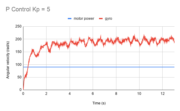
I attempted to get my system to oscillate by increasing the Kp values in order to implement Ki values, but due to some difficulty with implementing PID, it seems that I was unable to accomplish this task.

-
To test the angular speed of the robot, I wrote the script attached here
and uploaded it to the Artemis board. The script tells the robot to ramp up the motor power from 0 to 255 and then ramp down. While doing so, the robot can send back its sensor information via bluetooth about the gyroscope readings. I had to grease my wheels since it would barely move, but with a little grease, the maximum angular velocity came out to be approximately 1000 rads/s. While watching the robot spin, I noticed that my right wheel is capable of turning at lower motor power than my left wheel, causing it to rotate for in a circle rather than in axis while testing at lower motor power. The deadband left occurs at motor power of 108. Deadband right occurs at motor power of 125.
Lab 6(b): Odometry and Ground Truth in the Virtual Robot
Files
Procedure
- I downloaded the lab6 base code and followed the previous labs for setting up lab 6.
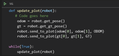
- I ran and edited the jupyter notebook code to plot the odometry and truth pose of the "robot".
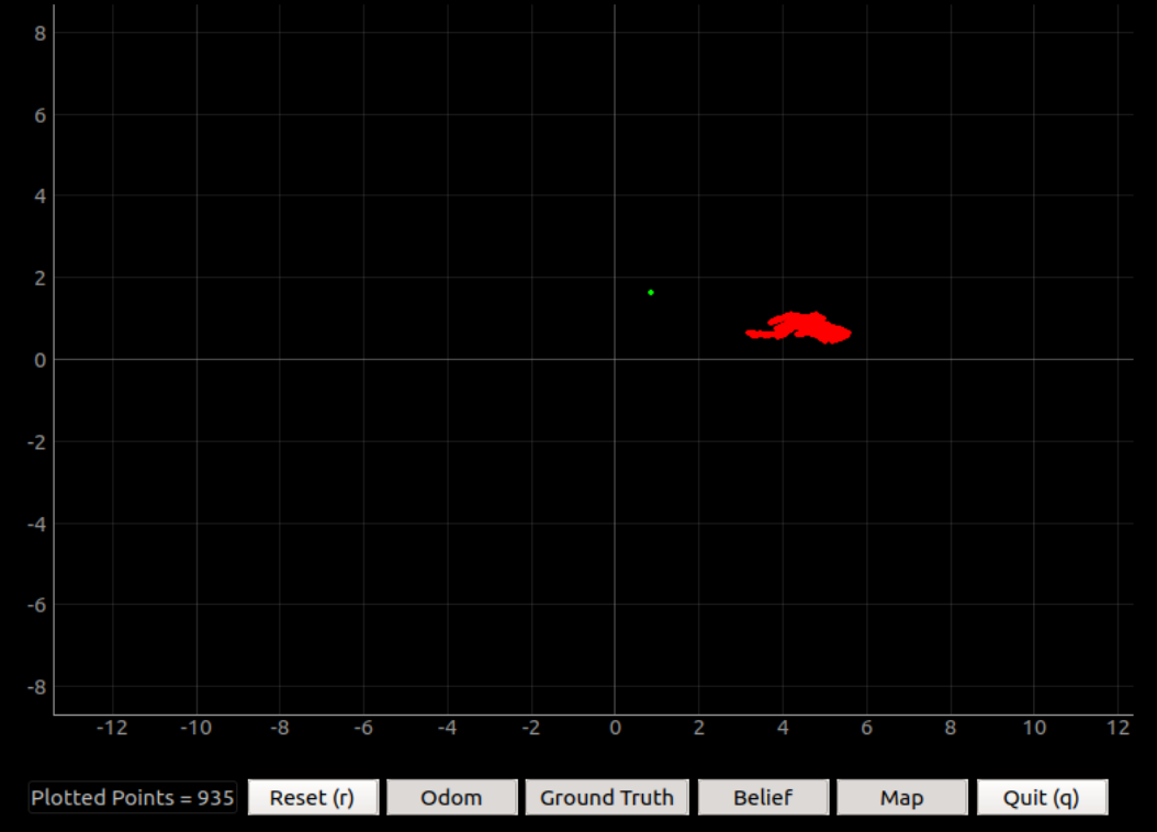
- First, I wanted to see how far off the odometry reading would be from the truth pose. I stationed my robot for a long period of time. As seen in the image below, the offset was substantial. I could also see that when the robot is stationary, the odometry position had significant amount of noise and was able to conclude that the odometry is best used for moving objects. (The green is truth pose and red is the odometry reading).
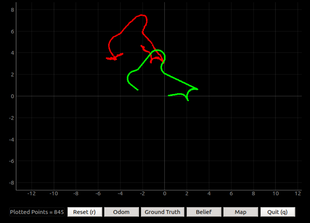
- Afterwards, I moved the robot around the map to see how well the odometry follows the truth pose. The general shape of the path is maintained. It seems that when the robot is moving, the odometry keeps up with the truth pose well with a consistent offset, but at points when it stops, the data becomes noisy and unreliable.