Lab 5(a): Obstacle Avoidance
Objective
To enable the robot to perform obstacle avoidance by equipping the robot with distance sensors.
Materials
- SparkFun RedBoard Artemis Nano
- USB A-to-C cable
- 4m ToF sensor
- 20cm proximity sensor
- Li-Ion 3.7V 400 or 500mAh battery
- Sparkfun Qwiic motor driver
- R/C stunt car and NiCad battery
- Qwiic connector
- Gray target
- Ruler or graph paper
- Double sided tape
- Screwdriver (Phillips or flathead)
- (optional) Wirecutter
My Code
Procedure
Proximity Sensor
- In the Arduino library manager, I installed the SparkFun VCNL4040 Proximity Sensor Library.
- I connected the proximity sensor (VCNL4040) to the artemis board using a QWIIC connector.
- Then I scanned the I2C channel to find the sensor. I did this by going to File -> Examples -> Wire -> Example1_Wire and uploading the script to the Artemis board. In the serial monitor, I was able to see that the proximity sensor is connected through 0x60 channel, which is consistent with the proximity sensor datasheet.
- To test the proximity sensor, I uploaded the given script, Example4_AllReadings, to the Artemis board. I was able to get this script through File -> Examples -> SparkFun_VCNL4040_Proximity_Sensor_Library -> Example4_AllReadings. Once it is uploaded, the serial monitor will output approx value, distance, ambient light level and white level.
In order to compare the sensor reading with respect to the distance, I gathered sensor readings from three objects at distances from 1cm to 22cm. The three objects were a red wallet, a black wallet and a navy notebook. I chose these items because they had different colors and textures.
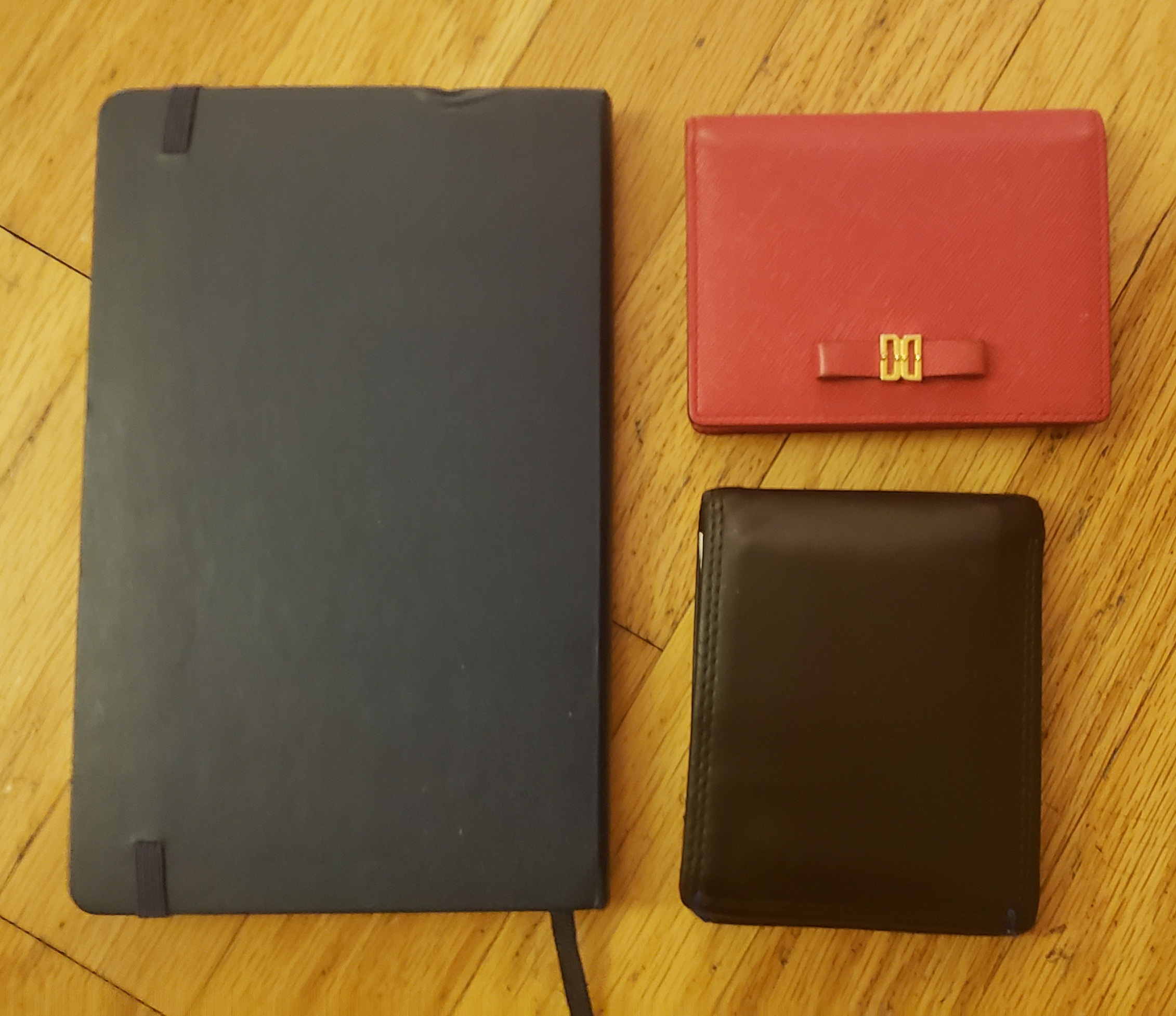
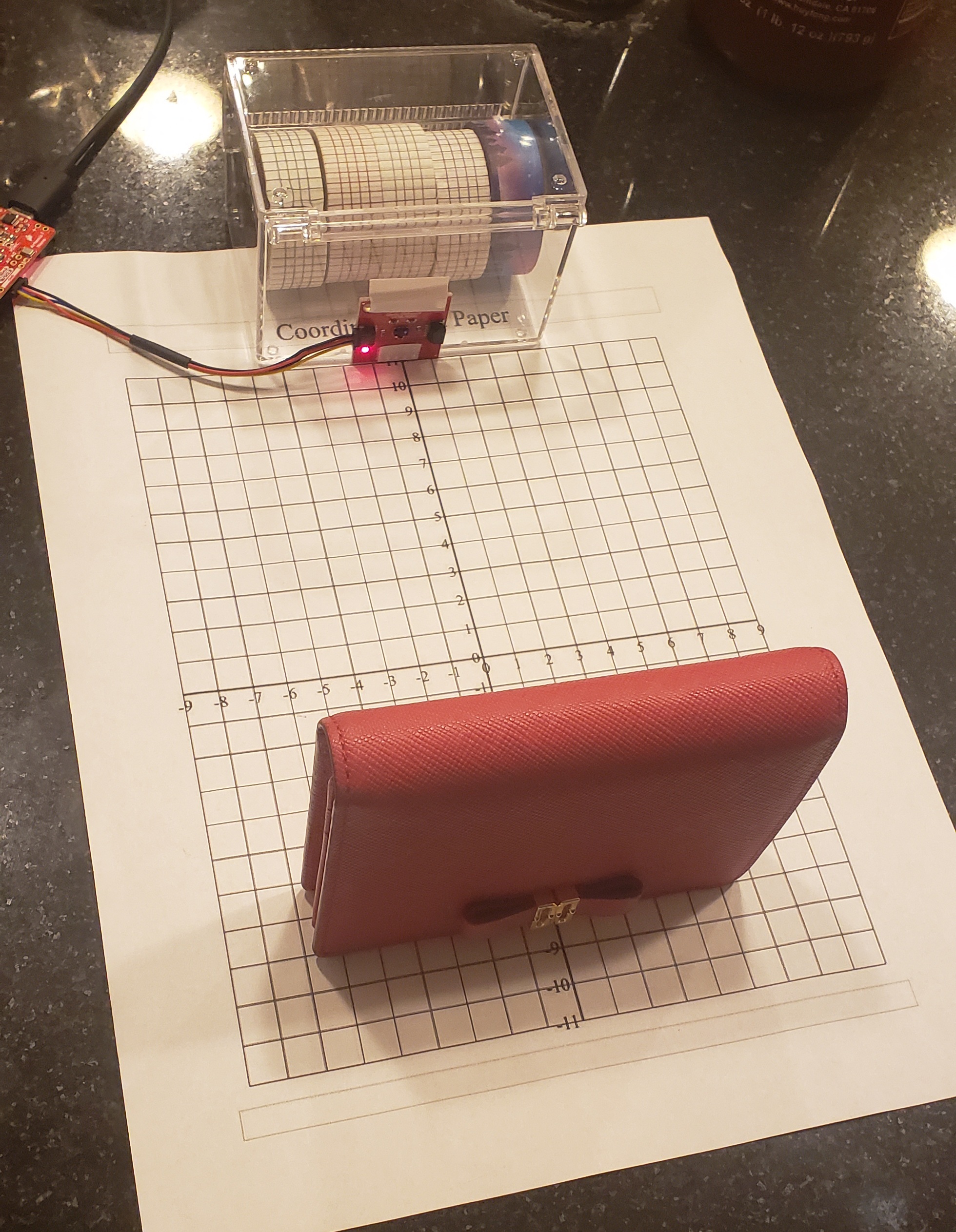
To collect data, I placed each object in front of the sensor and recorded the approximate value for each centimeter from 1cm to 22 cm. The setup looks like the image below. The paper beneath the sensor and the object is a grid sheet that measures in centimeters. I conducted this experiment for well-lit room and a dark room to see if the brightness of the environment affects the measurement data.
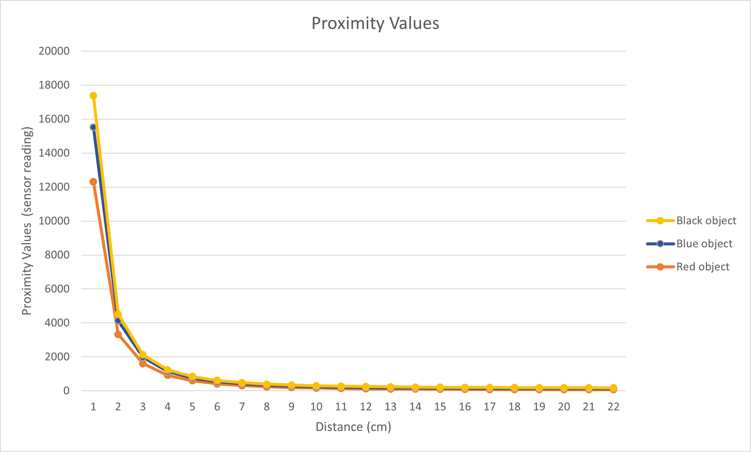
The sensor measurement for bright room can be seen here:
The same experiment was conducted with the red wallet in a dark room setting:
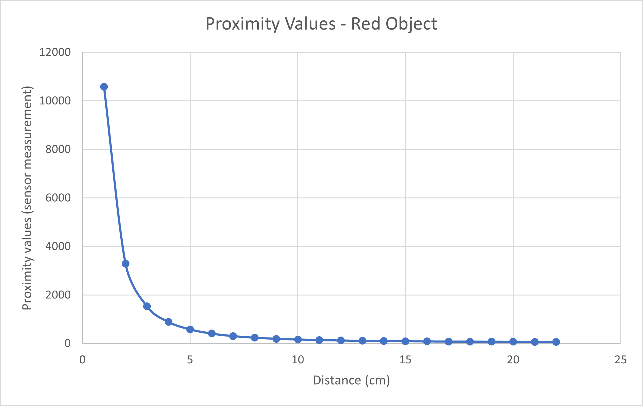
From the two graphs above, I could see that the darker shades produced higher sensor measurements. Black was also more reflective compared to the red wallet and the navy notebook, which might also contribute to the higher measurement values. Lighting, however, did not seem to create a huge difference in measurement with the red wallet. The trend and the values were extremely similar for the red wallet and I would infer that lighting is not correlated with measurement values.
Time of Flight Sensor
- First, I installed SparkFun VL53L1X 4m laser distance sensor library.
- Then I connected ToF sensor to the Artemis board using QWIIC connector.
- I scanned the I2C channel to find the sensor. You can do this by going to File -> Examples -> Wire -> Example1_Wire and uploading the script to the Artemis board. The channel was indicated in the serial monitor as 0x29, which is consistent with the ToF sensor datasheet.
- I tested the ToF senesor using the given script Example1_ReadDistance, which can be found by going to File -> Examples -> SparkFun_VL53L1X_4m_Laser_Distance_Sensor -> Example1_ReadDistance.
When I ran the script with the sensor 14 cm away from an object, it produced inaccurate measurements. The output looked like this: - In order to produce accurate measurements, I needed to calibrate the sensor. Thankfully, there is a calibration script provided by Arduino examples. (File -> Examples -> SparkFun_VL53L1X_4m_Laser_Distance_Sensor -> Example7_Calibration). However, the script did not run I uploaded it as it is given. I added
distanceSensor.startRanging()to the code and I was able to start calibrating. As given in the instructions of the script, I placed the 17% grayscale paper 14 cm away from the sensor and then I placed my hand in front of the sensor for one second in order to start the calibration. Afterwards, I uploaded Example1_ReadDistance again, I had more accurate values like this: - ToF sensor's accuracy, range, measurement, frequency and power consumption is dependent on the timing budget. I was able to play around with values of distanceSensor.setIntermeasurementPeriod(). I wanted the sensor to gather as frequency as possible, so I chose intermeasurement period to be 15, which was the lowest value allowed based on the datasheet.
- To optimize the ranging performance of the sensor, I will be expecting to use the short mode (distanceSensor.setDistanceModeShort()), which can detect up to 1.3 m. In Lab 3, I was able to determine maximum velocity of the robot to be 0.86 m/s. If the sensor has detection range of 1.3 m, the robot has 1.51 seconds to react to an obstacle, which should be enough time for the car to detect obstacles.
- The given Arduino script, Example3_StatusAndRate, was able to tell me whether or not the measurement was valid. After uploading the script, I moved an object quickly in front of the sensor to see that it would cause signal failure. If the robot or an obstacle moves too quickly, it will not be able to collect a valid measurement. For implementation in the future, I would have to toss out "bad" data or slow down my robot to collect valid measurements.
Obstacle Avoidance
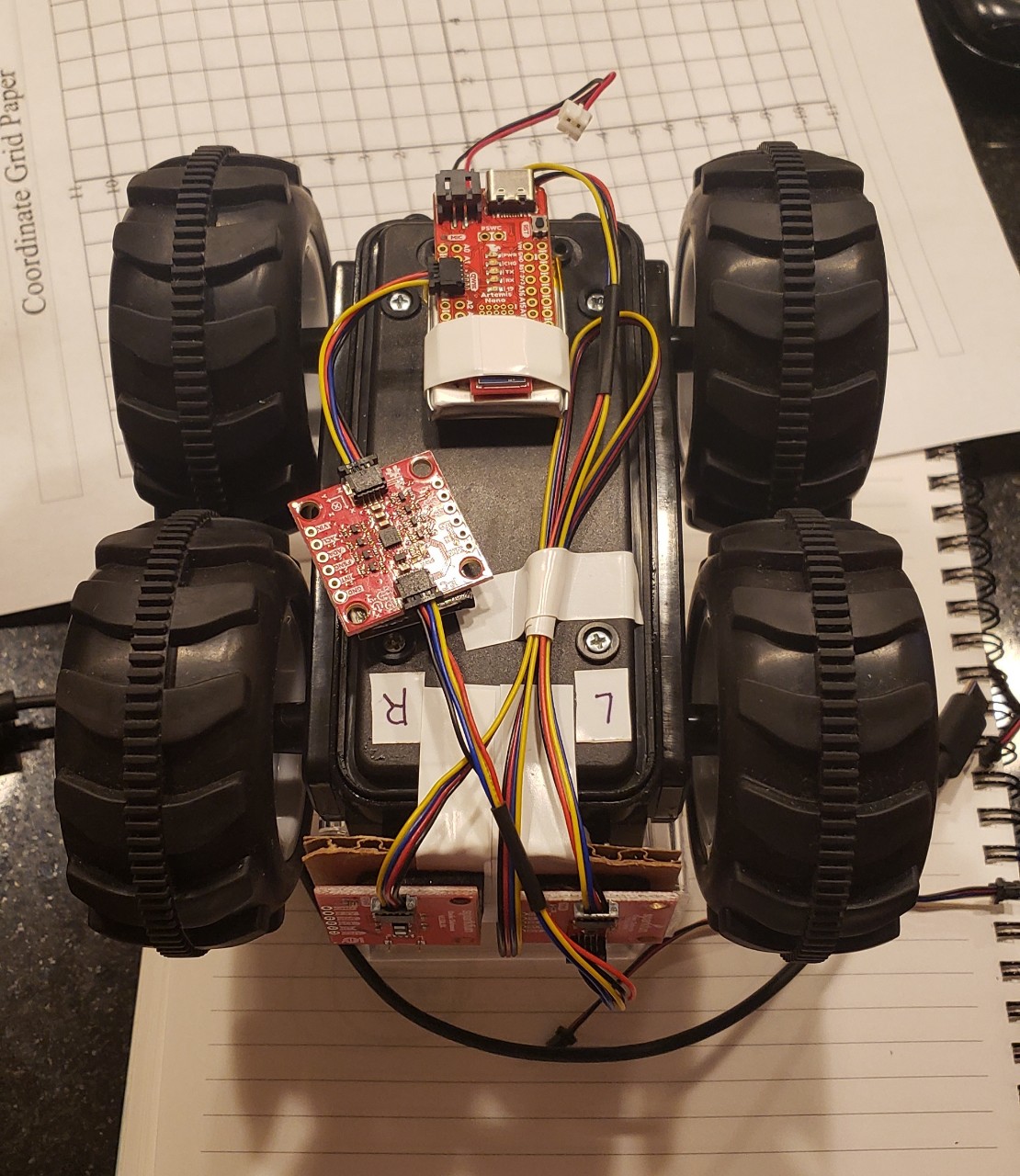
- I mounted the sensors, Li-Ion battery, and processor onto the car using the daisy chain method. I used some cardboard to create a flat surface for the sensors to mount on.
- Fun fact: I didn't know what daisy chain was and learned that its not a chain of daisies, but rather a series of sensors (but its a cute name for it).
- I connected another QWIIC connector to the motor driver and then brought it outside of the casing. When its fully assembled, it looks like this:
- I was able to code the robot and have it react to my hand in the video shown below. When it detects an obstacle, it moves backwards and then rotates, which is why the video may show the robot moving few seconds after it detects my hand. (Also, the robot in the video is not my robot because my ToF sensor broke on Sunday night, but slight shoutout to Charles Barreto for testing my code).
Lab 5(b): Obstacle Avoidance on your virtual robot
Objective
To enable the robot to perform obstacle avoidance in simulation.
My Code
Process
I downloaded the lab5 file and then set it up in the VM. Then I ran the simulator along with Jupyter lab in order to test my virtual obstacle avoidance. The velocity settings and obstacle detection range were determined by trial and error. It seemed that velocity of 0.7m/s most ideal and gives the "robot" enough time to process the measurement information and act on the information. When I chose larger values for velocity, the robot would crash into the wall without having a chance to recognize that it was getting too close to the wall. I also chose the threshold distance between the robot and the obstacle to be 0.7m because this allowed the robot to have enough space even when it approached the wall from an acute angle. When I attempted to use a smaller distance value, it would work when the robot is facing the wall head on, but would crash into the walls often when coming in from the side. I set the linear and angular velocity to be -0.1 and -1.5, respectively for 0.5 seconds because the linear velocity would allow the robot to back up slightly in case it has gotten too close to the wall and the angular velocity would allow the robot to turn away from the wall. If I made the linear velocity any larger, it would often bump into a different wall while backing up, especially in corner spaces or the small hallway spaces on the map. My code seems to work well most of the time, but it can't be helped that the robot does not have sensors on its side. The robot would sometimes crash because it fails to see an edge of a wall in front of itself or it can't detect that it got too close to the wall when coming in from the side. To prevent these crashes completely, robot would need more information about its environment through more sensors.
